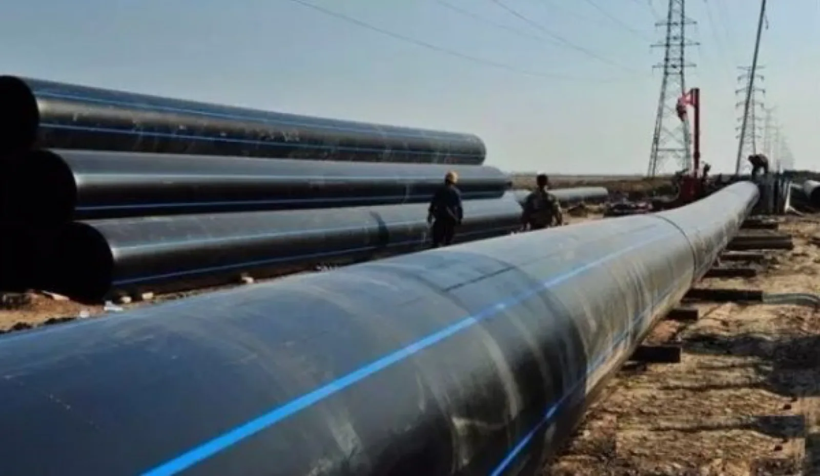
Most irrigation enquiries we receive arrive as a flat list: so many metres of pipe, so many elbows, so many tees. The list is usually correct in quantity and wrong in structure, because an irrigation network is not one pressure system. It is three or four systems in series, each operating in a different pressure band, each with a different failure mode, and each with a different sensible connection method.
The pump discharges into a mainline at one pressure. A control valve drops it. A pressure regulator drops it again. By the time water reaches an emitter, it may be operating at a quarter of the pressure the mainline sees. If you specify one pressure class and one fitting family across all of that, you have either overpaid on the laterals or underspecified the mainline. Both happen, and the second one is the expensive mistake.
This guide walks the network from pump to emitter, states what is actually written in the governing standards, and is explicit about where our own product range fits and where it stops. We manufacture pressure pipe up to Φ110 mm, published diameter by diameter with the wall thickness for each. That ceiling is a real boundary — a manufacturing limit, not a gap in what we will tell you — and pretending otherwise would waste your time and ours.
EN 12201-2:2024 is the European standard for polyethylene pipes in water supply and in pressurised drainage and sewerage. Its scope covers PE pipes for buried and above ground applications, for water for human consumption, raw water prior to treatment, drains and sewers under pressure, vacuum sewer systems, and water for other purposes. It defines materials PE 40 (limited to dn up to 63 mm, or 90 mm under some national forewords), PE 80, PE 100, and — added in the 2024 revision — PE 100-RC. It covers nominal pressures PN 4 to PN 25 bar, SDR series SDR 6, 7.4, 9, 11, 13.6 and 17, and diameters from 16 mm to 3000 mm nominal outside diameter. Industrial applications are excluded; those sit under EN ISO 15494.
Irrigation is not called out by name anywhere in that scope. It falls under “water for other purposes.”
ISO 4427-2:2019 reads the same way. Its Clause 1 scope covers PE pipes “for buried or above ground applications” conveying water for human consumption, raw water prior to treatment, drainage and sewerage under pressure, vacuum sewer systems, and “water for other purposes.”
Why this matters commercially: there is no such thing as an “irrigation-grade” PE pipe standard that a supplier can hold up as a category-specific credential. When a datasheet claims an irrigation-specific pressure classification, ask which clause of which standard it comes from. The pipe standards classify by material, SDR and PN — not by whether the water ends up in a crop, a cooling tower or a tap. If those three designations are running together in your specification, our guide to DN, SDR and PN sets out what each one actually fixes.
We should also flag, in the interest of not repeating a claim we cannot support: there are widely circulated colour-code tables for irrigation pipe (PN4 yellow, PN6 red, PN10 blue, PN16 green, and similar). We searched for a standards-body or industry-association source for those and found none — the tables appear only on manufacturer marketing sites. We are not reproducing them here, and we would treat any supplier who cites them as a standard with caution.
ISO 4427-2:2019 states its applicable conditions explicitly in Clause 1. There are two, and both are routinely dropped when pressure ratings get quoted in commercial documents:
The second condition is the one that bites in irrigation, and it bites hardest in exactly the markets where irrigation projects are largest. A PN rating is a declaration made at 20 °C. Above that reference temperature, derating is required. A black PE lateral lying on the surface in the Gulf, in North Africa or in sub-Saharan Africa in July is not at 20 °C, and neither is the water standing in it at midday.
We are not going to hand you a derating multiplier, because we have not read one in a primary source. The honest instruction is: take the derating factors from ISO 4427-1:2019 Annex A (or the equivalent annex of EN 12201-1) for your actual design temperature, and apply them before you compare pressure classes across suppliers. If a competitor’s quotation and ours both say PN16 and neither states the reference temperature, the two numbers are not yet comparable.
One related note on where we stop short. ISO 4427-2:2019 does contain an Annex C, “Relationship between PN, MRS, S and SDR,” listed on page 19 of the contents. It is informative rather than normative. The numeric table itself sits behind the paywall, and we did not read it — so this guide asserts no specific SDR-to-PN number pairs. The commonly circulated conversion formula and its design coefficient are likewise something we could only find on vendor blogs, not in the standards text, so they are absent here by choice rather than oversight.
The useful way to structure an irrigation bill of quantities is by hydraulic tier. Here is the framework we use when reading a drawing, with the fitting and material logic attached to each level.
| Tier | Hydraulic role | What governs the sizing decision | Typical connection logic | Our range at this tier |
|---|---|---|---|---|
| Mainline (pump to zone valves) | Carries full system flow at the highest pressure in the network; usually buried | Total design flow and pump discharge pressure; surge allowance; burial and traffic loading | Butt fusion or electrofusion on larger PE; flanged transitions at valves and pump house | Outside our range above Φ110. DN150–400 mainlines we cannot supply |
| Submain / manifold (valve to laterals) | Distributes zone flow along a header; pressure already reduced by the zone valve | Zone flow only, not system flow; allowable pressure variation along the header | Compression, electrofusion or solvent-weld depending on material; frequent branch takeoffs | Yes — HDPE PN16 and UPVC/CPVC 806 PN16, all nine diameters Φ20–Φ110, walls published per size |
| Lateral / dripline (header to emitters) | Delivers water to individual emission points at low, tightly controlled pressure | Emitter flow rate, emitter spacing, and maximum run length at the available inlet pressure | Barbed or compression connectors sized to the dripline; end flush caps | No — we do not manufacture dripline or emitters |
| Ancillary (filtration, air release, flush) | Protects emitters from clogging; manages air and sediment | Emitter orifice size dictates filtration mesh; topography dictates air valve placement | Threaded and flanged assemblies at the control head | Partly — UPVC ball valves and brass threaded transitions (per our catalogue) |
Reading down the right-hand column tells you our honest position immediately. We are a submain and distribution supplier for irrigation, plus the threaded and valve hardware around it. We are not a mainline supplier at municipal diameters and we are not a dripline supplier. Those are two different conversations with two different vendors, and a project of any size will involve both.
The governing standard at the emission end is ISO 9261:2004, “Agricultural irrigation equipment — Emitters and emitting pipe — Specification and test methods.” Its Clause 1 scope applies to emitters, emitting and dripping (trickling) pipes, hoses including collapsible hoses (“tapes”) and tubing of which emitting units form an integral part, with or without pressure regulation, with flow rates not exceeding 24 l/h per outlet (except during flushing), and to fittings dedicated to connecting emitting pipes, hoses and tubing.
Two exclusions in that scope are worth knowing. The standard does not apply to porous pipe — pipe that is porous along its entire length — and it does not cover performance as regards clogging. That second exclusion matters: clogging is the single most common cause of drip system failure, and the emitter standard explicitly does not address it. Clogging is managed by filtration and flushing design, not by buying a compliant emitter.
ISO 9261’s terms and definitions also give the distinction that drives the whole lateral design. A “regulated” emitter or emitting pipe — equivalently, a pressure compensating one — is defined as one which maintains a relatively constant flow rate at varying water pressures at the inlet, within limits specified by the manufacturer. An “unregulated” or non-pressure-compensating emitter is one whose flow rate varies with inlet water pressure. The standard further defines minimum and maximum working pressure as the lowest and highest inlet pressures recommended by the manufacturer to ensure proper operation, and defines a “non-leakage” emitter as one whose flow is zero below a threshold inlet pressure.
Note the structure of those definitions: the limits are set by the manufacturer and declared, not fixed by the standard. So when someone asks what pressure a dripline runs at, the standards-correct answer is that it depends on the specific product and you must read its declaration.
Here is where the tier framework earns its keep. Drip and sprinkler zones do not want the same pressure, and a network serving both cannot be regulated as one system. The figures below are from named manufacturer technical documents — they are product-specific, and we present them as such rather than as category norms.
| Parameter | Pressure-compensating dripline (Netafim Techline CV / HCVXR) |
Rotor sprinkler (Rain Bird 5000 Series) |
Design consequence |
|---|---|---|---|
| Operating pressure range | CV: 14.5–58 psi (1.0–4.0 bar) compensation range. HCVXR: 21.8–58 psi (1.5–4.0 bar) | 25–65 psi (1.7–4.5 bar) | Sprinkler zones run higher at the top and narrower at the bottom; they cannot share a regulator setting with drip |
| Ceiling | Maximum system pressure 58 psi | Upper spec limit 65 psi; PRS version regulates to precisely 45 psi at each head | A pressure that is normal for a rotor is at or over the drip system’s stated maximum |
| Filtration | Recommended minimum 120 mesh; guide states finer mesh “is not necessary and may require more frequent cleaning” | Not the governing constraint for rotor selection | Drip needs a filtration station in the control head that sprinkler zones do not |
| Flow per outlet | Emitter flows 0.26–1.16 GPH | 0.76–9.63 gpm (3.0–36.6 l/m) per head | Roughly three orders of magnitude apart per outlet — submain sizing differs completely |
| Coverage geometry | Emitter spacing 12″ / 18″ / 24″; lateral spacing 12″–24″ by soil and planting | Radius 25–50 ft (7.6–15.2 m) | Drip laterals are a dense grid; sprinkler is a sparse point network |
| Inlet connection | Product-specific barb/compression connectors | 3/4″ NPT female bottom threaded inlet | Threaded transition hardware is needed at the sprinkler riser, not at the dripline |
Conditions on the drip column: these are pressure-compensating 17 mm-class PE driplines (0.560″ ID × 0.660″ OD, 0.050″ wall), not generic drip tape, and both declare ISO 9261 compliance. The design guide instructs that pressure-regulating valves must bring zones to between 14 and 58 psi for Techline CV and 21.8 to 58 psi for HCVXR. Conditions on the sprinkler column: this is one rotor model from one manufacturer. We could not access a second manufacturer’s rotor documentation, so we deliberately do not generalise 25–65 psi to “sprinklers” as a category — treat it as one verified data point, not a class norm.
A point that is frequently missed in layout drawings: the maximum run length of a drip lateral is a function of its inlet pressure. It is not a fixed catalogue number.
The Netafim design guide tabulates maximum lateral length against inlet pressure from 20/25 psi up to 60 psi, and gives a worked example that shows the mechanism plainly: “If you have a 295′ lateral of 0.6 GPH/12″ Techline CV, it will need 35 psi to operate properly. If it is from 296’–340′, it will need 45 psi.”
Read that backwards and it becomes a submain positioning rule. If your available zone pressure is fixed by the regulator, your maximum lateral length is fixed with it — and therefore the maximum spacing between submains is fixed too. Push the laterals longer and you must raise zone pressure, which pushes you toward the 58 psi system ceiling. The layout, the pressure setting and the submain spacing are one decision, not three.
The same guide notes that headers “may be PVC, polyethylene or in zones under 5 GPM, Techline HCVXR and CV or Techline.” That is the tier where a PE or UPVC supplier is actually being specified — and it is our tier.
Emitter flow rate and spacing are not free choices. The Netafim Table 1 guidelines tie both to soil type:
| Soil type | Techline HCVXR emitter flow | Techline CV emitter flow | Emitter spacing (turf) |
|---|---|---|---|
| Clay | 0.33 GPH | 0.26 GPH | 18″ |
| Loam | 0.53 GPH | 0.4 GPH | 12″ |
| Sandy | 0.77 GPH | 0.6 GPH | 12″ |
| Coarse | 1.16 GPH | 0.9 GPH | 12″ |
The guide carries a qualifier worth reproducing: “0.4, 0.6 and 0.9 GPH are nominal flow rates. Actual flow rates used in the calculations are 0.42, 0.61 and 0.92 GPH.” Available emitter spacings are 12″, 18″ and 24″; lateral row spacing varies 12″–24″ by soil and planting.
The chain runs: soil type → emitter flow → emitters per lateral → lateral flow → number of laterals per submain → submain diameter. A coarse soil needing 1.16 GPH emitters generates roughly three and a half times the lateral flow of a clay soil at 0.33 GPH for the same emitter count. That difference lands directly on the submain size — which is the pipe you would buy from us. Soil survey data is a purchasing input, not just an agronomic one.
Burial depth is an area where confident numbers circulate freely and sources evaporate under examination. Here is the honest split.
Verified, with conditions attached. For subsurface dripline in landscape and turf applications, the Netafim Techline guidelines state: for turf, “Bury evenly throughout the zone from 4″ to 6″” (approximately 100–150 mm); for shrub and groundcover, “On-surface or bury evenly throughout the zone to a maximum of 6″.” Installation notes add that in areas where mechanical aeration will be used, you “bury the Techline 6″ below final grade and ensure aeration does not exceed 4″.” This is landscape and turf SDI depth — not agricultural row-crop SDI depth, and not buried mainline depth. Do not extrapolate it to either.
Verified as a regulation, in one jurisdiction only. The Water Supply (Water Fittings) Regulations 1999 for England and Wales, Regulation 5 and its Table, item 4(i), make notifiable to the water undertaker “any water system laid outside a building and either less than 750mm or more than 1350mm below ground level.” The same regulation’s Table, item 4(h), lists “a garden watering system unless designed to be operated by hand” as itself a notifiable installation. That is a UK statutory notification trigger for water fittings and service pipes — not a depth requirement in itself, not a pan-European figure and not an agricultural irrigation figure.
Not stated here, because we could not verify it. The governing European document for buried water pipe installation is EN 805, “Water supply — Requirements for systems and components outside buildings,” covering water supply systems outside buildings including mains and service pipes, plus installation, site testing and commissioning. We confirmed its clause structure — Section 9.2 “Pipe trenches” including depth of cover, Section 9.2.3 “Bedding,” and Section 10 “Testing of pipelines” — but we did not obtain the numeric values inside those clauses. Those figures circulate on distributor blogs attributed to EN 805, while the blogs’ own stated basis is a national water industry specification rather than EN 805 itself. We will not put a number under an EN 805 heading that we have not read in EN 805. (EN 1610 is the companion standard for drains and sewers.)
Similarly absent: agricultural SDI burial depths from extension services (the sources we reached gave mutually contradictory ranges), and drip system flushing velocity (the Netafim design guide text contains no flushing velocity figure). We found no citable basis for either, so neither appears above.
This is the single most useful thing in this guide for someone writing a specification.
The Netafim design guide states that Techline fittings are “designed to allow usage with operating pressures up to 58 psi,” and in its air-testing section instructs that “Techline HCVXR and CV fittings are rated to 58 psi, so the air pressure must be adjusted… 58 psi or less.”
So the 58 psi ceiling that governs that drip system is a fitting limit as much as a dripline limit. The system’s pressure class is set by its weakest component, and in irrigation networks the weakest component is very often a connector, not a pipe.
The practical consequence: a bill of quantities that specifies pipe pressure class carefully and then lists fittings generically has not actually specified a pressure class at all. When you evaluate quotations, ask each supplier for the pressure rating of the fittings, separately from the pipe. The answers will differ more than the pipe ratings do.
Now the direct answer to what we can supply into an irrigation network, stated against the tier framework above.
Our HDPE pressure pipe range is PN16 across nine diameters, Φ20 to Φ110. We produce two compression fitting series — 603 and 604 — which are mechanical, no-weld connections, covering the same Φ20–Φ110 span as the pipe. The full published wall thickness table is below; there are no gaps in it, so you can size a submain against declared product data rather than against an assumed SDR.
| Outside diameter (mm) | HDPE PN16 wall (mm) | UPVC/CPVC 806 WP55 PN16 wall (mm) |
|---|---|---|
| 20 | 2.3 | 2.0 |
| 25 | 2.3 | 2.0 |
| 32 | 3.0 | 2.4 |
| 40 | 3.7 | 3.0 |
| 50 | 4.6 | 3.7 |
| 63 | 5.8 | 4.7 |
| 75 | 6.8 | 5.6 |
| 90 | 8.2 | 6.7 |
| 110 | 10.0 | 7.2 |
Both columns stop at Φ110 because that is where our pressure pipe extrusion stops — the table ends where the product range ends, not where the data does. UPVC/CPVC 806 pipe is supplied in 4 m lengths. Note that the elevated-temperature description in our catalogue (95–120 °C (CPVC grade, per our catalogue)) is written against CPVC, which is why we refer to this as the UPVC/CPVC 806 system rather than attributing a CPVC temperature rating to UPVC on its own; for an above-ground irrigation submain in a hot climate, that distinction is worth settling at enquiry stage.
A necessary transparency note on marking. Our HDPE pipe body carries the printed marking “GERMANY STANDARD DIN8077/8078.” That numbering is in fact the DIN standard pair for polypropylene; the polyethylene pair is DIN 8074/8075. We report what is printed on the pipe as printed. We do not claim the pipe is manufactured to or conforms to DIN 8077/8078, because for a PE pipe that would be the wrong standard reference. If your specification requires a stated PE standard conformity, raise it with us at enquiry stage so it is resolved on paper before anything ships.
| Irrigation network need | Can we serve it? | Product line (per our catalogue) | Honest note |
|---|---|---|---|
| Buried mainline, DN150–400 | No | — | Our pressure pipe stops at Φ110. This is a hard manufacturing boundary, not a stock issue |
| Submain / manifold up to Φ110 | Yes | HDPE PN16, nine sizes Φ20×2.3 / 25×2.3 / 32×3.0 / 40×3.7 / 50×4.6 / 63×5.8 / 75×6.8 / 90×8.2 / 110×10.0, with 603 / 604 compression fittings Φ20–Φ110 | Compression means no fusion plant on site — relevant on dispersed field sites |
| Submain in rigid pipe up to Φ110 | Yes | UPVC/CPVC 806 PN16, WP55 pipe in nine sizes Φ20×2.0 / 25×2.0 / 32×2.4 / 40×3.0 / 50×3.7 / 63×4.7 / 75×5.6 / 90×6.7 / 110×7.2, 4 m lengths; 1806 fitting series Φ20–Φ110, 203 items including ball valves and solvent cement | Solvent-weld system; UV exposure of above-ground UPVC is a separate design question |
| Zone isolation and manual control valves | Yes | UPVC ball valves within the 1806 series | Manual isolation, not automated zone control or pressure regulation |
| Threaded transitions to pumps, filters, risers | Partly | Brass series 2405, 1/4″ to 1″; threaded transition fittings within 603 / 604 | Brass range tops out at 1″ — larger threaded transitions are outside it |
| Dripline, emitters, drip tape | No | — | We do not manufacture emitting pipe or emitters of any kind |
| Filtration stations, air release valves | No | — | Specialist irrigation control-head equipment; source separately |
| Pump house / building-side hot and cold service | Yes, limited | PPR PN20 series 1103, pipe in 20×2.8 / 25×3.5 / 32×4.4 mm only, 4 m; 1138 fitting series, 75 items | PPR pipe range is only those three sizes — small-bore service work, not distribution |
| Non-pressure field drainage | Yes | PVC 902 drainage pipe Φ32–110 (walls 1.6–2.2 mm, 4 m lengths); 1902 fittings to Φ160 — non-pressure only | Must never be used anywhere in the pressurised network |
Read that table honestly and the shape of a realistic relationship with us is visible. On a large agricultural scheme, we are a second-tier and distribution-hardware supplier alongside a large-diameter mainline vendor and a dripline vendor. On smaller schemes, greenhouse blocks, landscape irrigation and estate systems where nothing exceeds Φ110, we can cover the pipe and fittings for the whole pressurised distribution network.
Butt fusion and electrofusion produce a joint that is monolithic with the pipe, and on a large buried mainline that is generally what you want. But they require plant, power and a trained operator on site — and a fusion joint made badly in wind and dust is a liability that will not show up in a pressure test.
Irrigation submains have a different profile. They are frequently laid across dispersed field sites with no mains power, often reconfigured between seasons as cropping patterns change, and they accumulate a high count of branch takeoffs per hundred metres compared with a mainline. A mechanical joint that can be made with hand tools, checked visually, and taken apart and remade when the layout changes suits that pattern.
The trade-off is real and we will state it: a compression joint depends on correct assembly and correct O-ring seating in a way a fused joint does not, and it puts a mechanical component into the pressure boundary. Given the point above about fittings being the weakest link, that is a reason to specify the fitting rating explicitly and to train whoever assembles them.
Our own view, offered as experience rather than as a sourced fact: on networks at or below Φ110 with frequent takeoffs and seasonal reconfiguration, mechanical compression is usually the better operational choice; on a continuous buried run with no branches that will never be touched again, fusion has the advantage. Most schemes contain both situations — another argument for tiering the specification rather than standardising on one method.
Pulling the above into an order of operations. This is the sequence we use when a drawing arrives, and following it will produce an enquiry we can actually price.
In keeping with the rest of this guide, a plain statement of gaps on our side.
Our certifications include SKZ, CE, WRAS, DVGW, SGS, ISO 9001 and ISO 14001. Certificate numbers are Coming soon — we would rather publish nothing than publish a number we cannot substantiate on request. Irrigation project references, tonnages shipped and named client schemes are also Coming soon; we are not going to describe projects we cannot evidence. Pricing, MOQs and lead times are Coming soon as published figures, because for irrigation they genuinely depend on the diameter mix and fitting count rather than on a headline rate.
Wall thicknesses are not among those gaps. Our HDPE and UPVC/CPVC 806 pressure ranges are published size by size, every diameter, in the table above, and the PVC 902 drainage range is published the same way across its nine sizes (walls 1.6–2.2 mm, tabulated in full on the drainage product page). Nothing in those tables is back-calculated from an SDR formula. Where a wall thickness genuinely is not published, we say which range and why: our PEX range (2114 clamp and 2121 press series, Φ16–32) is catalogued by diameter only, with no wall thickness and no pressure class, and brass series 2405 is sized by thread rather than by wall. Neither of those is an irrigation distribution product, so neither affects the specification sequence above.
On the company itself: IFANNova is a French brand. Manufacturing is by Zhuji Fengfan Piping in Zhuji, Zhejiang, China — over 30 years of operation, 1000+ employees, supply into 118+ countries, 120,000 m² of production. We say this plainly because a buyer discovering the manufacturing origin at the shipping-documents stage is a buyer who will never order again.
Is there an irrigation-specific PE pipe standard I should be asking for?
Not as a named application. EN 12201-2:2024 and ISO 4427-2:2019 both place irrigation under “water for other purposes” rather than naming it. Specify by material, SDR/PN and standard version, and state your design temperature.
Can you supply the whole irrigation system?
No. We can supply the pressurised distribution network up to Φ110 — HDPE PN16 with 603/604 compression fittings, UPVC/CPVC 806 PN16 with the 1806 fitting series, ball valves and brass threaded transitions to 1″. Both pipe ranges are published with a wall thickness for every one of their nine diameters, so you can specify from the table rather than asking us for intermediate sizes. We do not make dripline, emitters, filtration stations or pipe above Φ110.
Does PN16 mean the pipe holds 16 bar in my field?
It means 16 bar under the standard’s stated conditions, which include a 20 °C reference temperature per ISO 4427-2:2019 Clause 1. Above that, derating applies. Take the factors from ISO 4427-1:2019 Annex A for your actual conditions.
Why do you not publish an SDR-to-PN conversion table?
Because the authoritative table sits in ISO 4427-2:2019 Annex C, which is behind the standard’s paywall, and we have not read it. We are not reproducing numbers we cannot verify against the source. You do not need it to specify from us: our pipe is supplied to a declared PN with the wall thickness published for every diameter — see the HDPE and UPVC/CPVC 806 tables above. Work from the declared wall, not from a conversion.
What burial depth should I use for the buried submain?
Take it from your local requirement or the relevant clause of EN 805 (Section 9.2, depth of cover, and 9.2.3, bedding). We verified the clause structure but not the numeric values inside it, so we are not quoting a figure. The UK’s 750–1350 mm band is a notification threshold for water fittings in England and Wales specifically — laying outside it makes the work notifiable to the water undertaker — and should not be treated as a universal irrigation figure.
Compression or fusion for irrigation submains?
Our view, as experience rather than a sourced claim: compression suits dispersed sites without power, frequent branch takeoffs and seasonal reconfiguration. Fusion suits continuous buried runs. Specify the fitting pressure rating explicitly either way.
Can I use your PVC 902 pipe for a low-pressure irrigation run?
No. PVC 902 is non-pressure drainage pipe. The pipe runs Φ32–110 with walls of 1.6–2.2 mm; only the 1902 fitting series extends to Φ160, so “902 up to Φ160” is a common misreading of our catalogue. Either way it has no place anywhere in a pressurised irrigation network at any pressure.
Do you supply PPR for irrigation?
Only for small-bore service work such as pump house connections. Our PPR PN20 pipe range is 20×2.8, 25×3.5 and 32×4.4 mm only — three sizes. It is not a distribution product.
The fastest way to get a useful answer from us is to send the zone layout with flows and the pressure available at each zone valve, rather than a quantity list. We will tell you within one working day which tiers of your network we can supply, which we cannot, and where your specification has a pressure class stated without the temperature it depends on.
If your mainline exceeds Φ110, we will say so immediately instead of quoting around it.
Send your irrigation network drawing and bill of quantities →
Socket fusion parameters for PP-R by diameter: heater at 260 ± 10 °C, heating 5–60 s, change-over max 4–10 s, insertion depth 14.5–40 mm.
Butt fusion, electrofusion and compression compared on process windows, not joint strength: PPI TR-33 heater 204-232 C, DVS 2207-1 200-220 C with 10x wall soak, ISO…
Cold joints cause most field butt fusion failures and ultrasonic inspection cannot detect them.
