Almost every fittings chart you will find online sorts by shape: elbow, tee, reducer, cap. That is only half of a purchase order line. A 90° elbow that changes direction is useless to you if its ends will not join to the pipe you have already bought, and the end connection — threaded, solvent-welded, fusion-welded, compression — is governed by an entirely different set of standards from the ones that govern the body shape.
So this page is organised on two axes at once:
What this page does not do is repeat sizing. DN, NPS, SDR, PN, schedule numbers, temperature derating and flange dimensions are all handled in detail on our pipe sizing charts reference, which quotes the governing clauses. Where a fitting decision depends on a sizing concept, we name it in one line and link across rather than restating it.
Every dimensional or scope figure below is attributed to a named standard with its version year. Figures describing our own products are marked (per our catalogue). Where a widely repeated industry rule of thumb could not be traced to a primary standard, we say so instead of printing it.
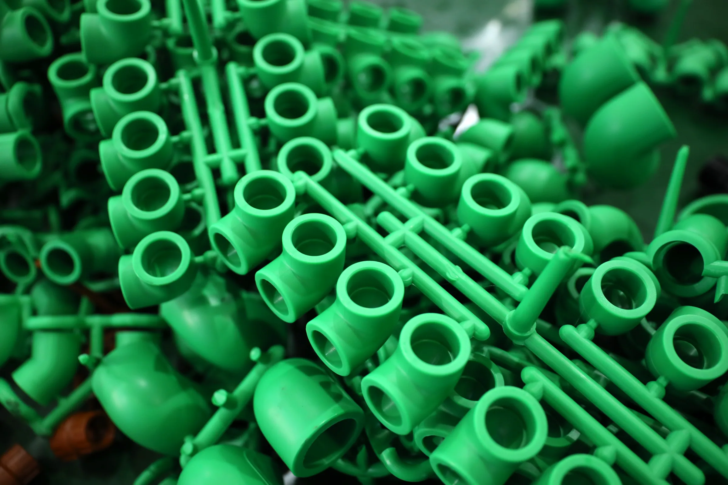
The job is to turn the run. The selection variables are the turn angle, the centreline radius, and whether the fitting also changes diameter while it turns.
ASME B16.9-2001, the standard for wrought factory-made buttwelding fittings, gives its scope in clause 1.1 as covering “overall dimensions, tolerances, ratings, testing, and markings for wrought factory-made buttwelding fittings in sizes NPS 1/2 through 48 (DN 15 through 1200)”. The direction-change categories it tabulates are visible in its own table titles: Table 3 “Dimensions of Long Radius Elbows”, Table 4 “Long Radius-Reducing Elbows”, Table 5 “Long Radius Returns”, Table 6 “Short Radius Elbows”, and Table 7 “Short Radius 180 Deg Returns” (ASME B16.9-2001).
That table structure tells you the real selection logic:
A note on a number we deliberately are not printing. You will very often see “long radius = 1.5 × NPS centre-to-end, short radius = 1.0 × NPS” quoted as if it were the definition. In ASME B16.9-2001, Tables 3 and 6 are per-size numeric tables; we could not locate a clause in the standard text that states the 1.5D/1.0D relationship as a formula. It circulates widely through distributor and blog pages, but that is not a primary source. Treat it as a common industry shorthand and take your actual centre-to-end from the dimension table for the specific size you are buying.
In our range (per our catalogue): direction-change fittings appear in every one of our series — the PPR 1138 series (75 items), the UPVC 1806 series (203 items), the HDPE 603 and 604 compression series, and the brass 2405 range in 1/4″ to 1″. Our production is plastics-led and stops at Φ110 for pressure lines, so the NPS 1/2–48 span of ASME B16.9 is far wider than anything we make; we cite it here because it is the clearest published taxonomy of direction-change shapes, not because we supply buttwelding steel fittings. We do not.
The job is to split one flow into two, or merge two into one. ASME B16.9-2001 tabulates these in Table 8 “Straight Tees and Crosses” and Table 9 “Reducing Outlet Tees and Reducing Outlet Crosses”.
Again the table split carries the selection rule. A straight tee has a branch the same size as the run. A reducing outlet tee has a smaller branch. The reducing outlet tee is the single most common fitting on a building services riser, because branches are almost always smaller than the main they come off — and specifying a straight tee plus a bushing instead is a frequent and avoidable error.
There is one scope limitation here that is worth more than it first appears. ASME B16.9-2001 clause 1.3, on fabricated fittings, states: “Fabricated laterals and other fittings employing circumferential or intersection welds are considered pipe fabrication, and are not within the scope of this Standard.”
In practice that means a lateral — an angled branch, typically 45° — is not a standard buttwelding fitting under B16.9. If your drawing calls for laterals, you are specifying pipe fabrication work, with the inspection, qualification and documentation load that comes with fabricated welds. Listing “lateral” in the same table as tees and crosses, as many published fittings charts do, quietly misrepresents what you are ordering.
In our range (per our catalogue): tees and reducing tees are present across the PPR 1138 (75 items), UPVC 1806 (203 items) and HDPE 603/604 series; cross-pattern items (Three Way Cross, Short Cross-Over, Crossing-the-Bridge) are carried in the PPR 1138 series only. Because our fittings are moulded plastics joined by solvent cement, socket fusion or compression rather than by welding, the B16.9 fabricated-lateral caveat does not apply to them in the same way — but the underlying design point does: an angled branch is a special item, not a shelf item, and for our lines it is Coming soon rather than something we will claim to stock.
The job is to move between two pipe sizes. There are two structurally different ways to do it, and they are not interchangeable.
The practical selection point that fittings charts usually skip: a bushing puts the size transition inside an existing joint, which means one component now carries two sealing interfaces. On a threaded line that is two thread engagements in series, each of which needs its own jointing medium. Where you have the physical length available, our engineering view — stated as opinion, not as a standard requirement — is that a reducer is the lower-risk component, and a reducing tee or reducing elbow is better still because it removes a joint entirely.
Note also from Family 1 and Family 2 that ASME B16.9-2001 treats reduction as something that can be built into a direction-change or branch fitting (Table 4 reducing elbows, Table 9 reducing outlet tees) rather than always requiring a dedicated reducer. Designing that way reduces joint count.
In our range (per our catalogue): reducers and reducing sockets are carried in the PPR 1138 and UPVC 1806 series. Our size envelope constrains what reductions are possible: PPR is manufactured only in 20 × 2.8, 25 × 3.5 and 32 × 4.4 mm (each in 4 m lengths), so PPR reductions are limited to combinations within 20/25/32 mm — above 32 mm is Coming soon. UPVC runs Φ20 × 2.0 to Φ110 × 7.2 in 4 m lengths, and HDPE runs Φ20 × 2.3 to Φ110 × 10, so reductions across that span are available in those lines. We publish per-size wall thickness across the full catalogue range for UPVC 806, HDPE and PVC 902 — see our pipe sizing charts for the complete nine-row tables. Where the catalogue genuinely does not list walls (PEX 2114/2121 and brass 2405), we say so and ask you to enquire rather than back-calculating a figure.
The job is to connect two lengths of pipe in a straight run, or to cross between two different joining systems. This family divides by whether the joint is meant to come apart again.
ISO 49:1994, titled “Malleable cast iron fittings threaded to ISO 7-1”, is the product standard covering exactly this group in the ISO system — elbows, tees, unions, caps and similar — for sizes 1/8 to 6, with the threads themselves specified separately by ISO 7-1. That division of labour is worth internalising: the fitting standard and the thread standard are two different documents, and a fitting can be dimensionally correct while its thread type is wrong for your mating part. Which brings us to the section that causes the most field trouble.
In our range (per our catalogue): couplings, unions and male/female threaded adaptors are present in the PPR 1138 and UPVC 1806 series; the HDPE 603 and 604 series are compression fittings offering no-fusion quick connection; and the brass 2405 range covers 1/4″ to 1″. PEX joining is served by the 2114 sliding-sleeve fittings (S16, S20) and the 2121 press fittings (16, 18, 20, 25, 26, 32 mm).
This is the highest-value section on the page, because a thread mismatch does not announce itself. The parts assemble. They tighten. They leak later, under pressure, behind a wall.
There are two families of pipe thread, and they exist for two different purposes.
Sealing threads — ISO 7-1. ISO 7-1:1994 clause 1 states its scope as covering “the requirements for thread form, dimensions, tolerances and designation for jointing pipe threads, sizes 1/16 to 6 inclusive, for joints made pressure-tight by the mating of the threads. These threads are taper external, parallel internal or taper internal and are intended for use with pipes suitable for threading and for valves, fittings or other pipeline equipment interconnected by threaded joints.”
Its clause 4 symbols are the ones printed on the fitting:
Fastening threads — ISO 228-1. ISO 228-1:2000 clause 1 covers “the requirements for thread form, dimensions, tolerances and designation for fastening pipe threads, thread sizes 1/16 to 6 inclusive. Both internal and external threads are parallel threads, intended for the mechanical assembly of the component parts of fittings, cocks and valves, accessories, etc.” Its clause 3 defines the symbol: “G Pipe thread where pressure-tight joints are not made on the threads.”
The consequence is stated outright in the same clause 1: “These threads are not suitable as jointing threads where a pressure-tight joint is made on the thread. If assemblies with such threads must be made pressure-tight, this should be effected by compressing two tightening surfaces outside the threads, and by interposing an appropriate seal” (ISO 228-1:2000).
So a G thread requires a gasket or washer seating on a face outside the thread. The thread only holds the parts together. If you install a G fitting and rely on tape or paste in the thread, you have no designed seal.
Three further points from the standards that repeatedly catch people out:
The two standards cross-reference each other deliberately. ISO 7-1:1994 NOTE 2 says “For pipe threads where pressure-tight joints are not made on the threads, see ISO 228-1”, and ISO 228-1:2000 NOTE 1 says “For pipe threads where pressure-tight joints are made on the threads, see ISO 7-1.”
| Designation | Internal / external | Taper or parallel | Seals on the thread? | Source |
|---|---|---|---|---|
| R | External | Taper | Yes — jointing medium still required | ISO 7-1:1994 cl. 4 and cl. 1 |
| Rc | Internal | Taper | Yes — jointing medium still required | ISO 7-1:1994 cl. 4 and cl. 1 |
| Rp | Internal | Parallel | Yes — jointing medium still required | ISO 7-1:1994 cl. 4 and cl. 1 |
| G (no class) | Internal | Parallel | No — needs a seal on faces outside the thread | ISO 228-1:2000 cl. 1 and cl. 3 |
| G with class A or B | External | Parallel | No — A and B are external thread tolerance classes | ISO 228-1:2000 cl. 3 |
On designation format, ISO 228-1:2000 clause 3 defines “A Tighter class of tolerance of external pipe threads” and “B Wider class of tolerance of external pipe threads”, so a marking reads G 1/2 for the internal thread and G 1/2 A for a class A external thread. Clause 4 adds that “The profile of these threads is identical with that of the parallel thread specified in ISO 7-1. The internal and external threads covered by this part of ISO 228 are both parallel” — the profile is shared, the function is not. Both standards are the work of ISO/TC 5/SC 5.
The second thread trap is between the ISO/BSP family above and the American NPT family. Swagelok’s Thread and End Connection Identification Guide (MS-13-77) lists the characteristics side by side.
For NPT, “also known as ASME B1.20.1”, the guide gives: “Tapered thread (1° 47′); Truncation of roots and crests are flat; 60° thread angle; Pitch is measured in threads per inch.”
For ISO 7/1, “also known as EN 10226-1 and JIS B0203”, it gives: “Tapered thread (1° 47′); Truncation of roots and crests are rounded; 55° thread angle; Pitch is measured in threads per inch.”
Read those two together. The taper is identical at 1° 47′. The thread angle is not — 60° against 55° — and the root and crest treatment is flat against rounded. That is why the two will start to assemble and will not seal reliably. Same taper, different tooth.
It gets worse at exactly the sizes used most in building services. The same Swagelok guide warns: “Note: 1/2 and 3/4 in. ISO 7/1 and NPT threads can be difficult to identify because they are very close in design. Positive identification may not be possible without the use of an optical comparator.”
The measured figures on that page show why. At 1/2 in, ISO 7/1 has an outside diameter of 0.825 in (20.96 mm) at 14 threads per inch, while NPT has 0.832 in (21.14 mm), also at 14 threads per inch (Swagelok MS-13-77). Same pitch, roughly 0.2 mm apart on diameter. A thread gauge that only counts pitch will not tell them apart.
| Property | NPT (ASME B1.20.1) | ISO 7/1 (EN 10226-1, JIS B0203) |
|---|---|---|
| Taper | 1° 47′ | 1° 47′ — identical |
| Thread angle | 60° | 55° |
| Roots and crests | Flat truncation | Rounded truncation |
| Pitch measurement | Threads per inch | Threads per inch |
| 1/2 in outside diameter | 0.832 in / 21.14 mm, 14 TPI | 0.825 in / 20.96 mm, 14 TPI |
All values in this table are from Swagelok MS-13-77. ASME’s own listing for the NPT standard gives the title “B1.20.1 – Pipe Threads, General Purpose, Inch”, current edition B1.20.1-2013 (R2018), described as covering the dimensions and gaging of the most common inch pipe threads and encompassing NPT, NPSC, NPTR, NPSM and NPSL. The full scope clause of B1.20.1 sits behind a paid standard, so we quote ASME’s own product description rather than the clause text.
On the European side, BS EN 10226-1:2004 is titled “Pipe threads where pressure tight joints are made on the threads – Taper external threads and parallel internal threads. Part 1: Dimensions, tolerances and designation”, covering “jointing pipe threads, sizes 1/16 to 6 inclusive” and stating that “An appropriate thread sealant or jointing compound should be used on the thread to ensure pressure-tight joints.” We describe EN 10226-1 as the European counterpart to ISO 7-1 and stop there. The claim that the two are dimensionally identical and fully interchangeable is repeated widely, but we could not open a CEN or BSI primary text confirming it, so we do not assert it.
One more practical item from Swagelok MS-13-77 on tapered threads generally: “The seal is designed to take place between the tapered threads”; “Tapered pipe threads always need a sealant to seal system fluids and reduce the potential for galling of the threads”; and, on tightening, “After following the sealant and lubricant application instructions, the amount of tightening is discretionary. There is no standard for torque or number of turns.” If your installation specification cites a torque figure or a turns-past-hand-tight figure for tapered pipe thread, it is a house rule, not a standard requirement.
Thread is one of several ways to attach a fitting, and for plastics it is usually the minority case. The choice of end connection determines your tooling, your labour skill requirement, and whether the joint can be made in a trench in bad weather.
Fusion (thermoplastic). ISO 15874-1:2013 clause 1 sets out the polypropylene system scope: it “specifies the general aspects of polypropylene (PP) piping systems intended to be used for hot and cold water installations within buildings for the conveyance of water whether or not intended for human consumption (domestic systems), and for heating systems, under design pressures and temperatures according to the class of application.” The series splits into Part 1 General, Part 2 Pipes, Part 3 Fittings, Part 5 Fitness for purpose of the system, and Part 7 Guidance for the assessment of conformity; the second edition brought PP-RCT material into scope.
ISO 15874-3 covers the fittings themselves and recognises four construction types: socket fusion fittings, electrofusion fittings, mechanical fittings, and fittings with incorporated inserts. That four-way split is the real menu for a PP system. Verified against the official ISO 15874-3:2013 preview text, clause 1, which lists socket fusion, electrofusion, mechanical, and incorporated-insert fittings.
On the workmanship side, ASTM F3722-24 “describes procedures for making joints with pressure-rated polypropylene (PP) pipe and fittings by means of heat fusion joining in, but not limited to, a field environment”, covering socket fusion, butt fusion, sidewall fusion and electrofusion, and applying to PP pipe and fittings made to ASTM F2389, CSA B137.11 or ISO 15874.
Compression. EN 1254-2:2021, “Copper and copper alloys – Plumbing fittings – Part 2: Compression fittings for use with copper tubes”, distinguishes two basic forms: Type A, non-manipulative, which carries a sealing element, and Type B, manipulative, which has no sealing element and instead requires the tube end to be worked. Its fitting ends run “from 6 mm to 108 mm” nominal diameter for joining copper tubes, the fittings are “designed for a service lifetime up to fifty years”, and the copper tube itself is expected to conform to EN 1057, with tube temper condition needing consideration.
Crucially, EN 1254 splits by what you are joining. Part 1 covers capillary fittings for soldering or brazing to copper tubes; Part 2 covers compression fittings for copper tubes; Part 3 (EN 1254-3:2021) covers “Compression fittings for use with plastics and multilayer pipes”; Part 4 covers threaded fittings (EN 1254-4:2021, which superseded the 1998 edition on fittings combining other end connections with capillary or compression ends); Part 5 covers short-end brazing fittings. Compression fittings for copper and compression fittings for plastic or multilayer pipe are separate standard parts and are not interchangeable — a distinction that is invisible on a delivery note and expensive on site.
Solvent cement. Used for our UPVC line. The joint is a chemical weld between socket and spigot, not a mechanical grip.
Socket-weld and threaded forged (metal). ASME B16.11 covers “ratings, dimensions, tolerances, marking and material requirements for socket-welding and threaded forged fittings”, with pressure classes of 2000, 3000 and 6000 for threaded ends and 3000, 6000 and 9000 for socket-welding ends. Its threaded ends reference NPT directly — the standard text requires thread length “not be less than L2 (effective length of external thread) required by the American National Standard for Pipe Threads (ASME B1.20.1)”. We list this family for completeness of the taxonomy; we do not manufacture forged steel fittings.
| End connection | Governing document cited here | Demountable? | Site tooling | In our range (per our catalogue) |
|---|---|---|---|---|
| Socket fusion (PP) | ISO 15874-3; ASTM F3722-24 | No | Heated tooling | PPR 1138 series, 75 items, 20/25/32 mm only |
| Electrofusion (PP) | ISO 15874-3; ASTM F3722-24 | No | Fusion control box | Coming soon |
| Solvent cement (UPVC) | Product line standard, see note below | No | Cement and applicator | UPVC 1806 series, 203 items incl. ball valves and solvent cement |
| Compression, plastics | EN 1254-3:2021 (as the standard family for plastics/multilayer) | Yes | Spanners only | HDPE 603 and 604 series, no-fusion quick-connect |
| Compression, copper | EN 1254-2:2021, Type A / Type B | Yes | Spanners; Type B needs tube-end work | Not manufactured by us |
| Threaded, sealing | ISO 7-1:1994 (R / Rc / Rp); ISO 49:1994 for MI fittings | Yes | Spanners plus jointing medium | Brass 2405 range, 1/4″–1″; threaded adaptors in 1138 and 1806 |
| Threaded, fastening only | ISO 228-1:2000 (G) — seal is outside the thread | Yes | Spanners plus gasket | Present as adaptor ends; gasket seal required |
| Sliding sleeve (PEX) | Manufacturer system | No | Expander and press tool | PEX 2114, S16 and S20 |
| Press (PEX) | Manufacturer system | No | Press tool and jaws | PEX 2121, 16/18/20/25/26/32 mm |
| Socket weld / forged threaded | ASME B16.11, Class 2000–9000 | Socket weld: no | Welding | Not manufactured by us |
| Buttweld | ASME B16.9-2001, NPS 1/2–48 | No | Welding | Not manufactured by us |
On the solvent cement row: we are not citing a clause because we did not verify a primary solvent-cement standard text in preparing this page, and we would rather leave the cell honest than fill it with a standard number we have not opened.
The job is to close a run. ASME B16.9-2001 tabulates these in Table 11 “Caps”. The distinction that matters on a materials list is direction: a cap goes over a pipe end or spigot; a plug goes into a socket or a female thread. Ordering one when you need the other is among the most common single-line errors on a fittings schedule, because both are described colloquially as “a stop end”.
Terminations do more work than their price suggests. They close off future-phase branches, they blank unused ports on manifolds, and during commissioning they are what allows a section to be pressure-tested independently of the rest of the system. If your fittings schedule has no caps or plugs on it, your test regime probably has not been thought through.
One further category from the same standard: Table 10 covers “Lap Joint Stub Ends”. A stub end is not a termination in the flow sense — it forms a flanged face, working with a backing flange so that the flange can rotate freely for bolt alignment. It appears here because it is the fitting people reach for when a run has to terminate at equipment rather than terminate blind. Flange dimensional systems and where DN/NPS equivalence physically fails are covered on our pipe sizing charts page.
In our range (per our catalogue): caps and plugs are carried in the PPR 1138 and UPVC 1806 series. The PVC 902 drainage range — 902 pipe Φ32–110, 1902 fittings Φ32–160 — also includes termination items — but note the standing limitation on that line: the 902 range is non-pressure drainage only, including its Φ160 size, and must never be specified for pressure duty.
Most fittings charts exclude valves on the grounds that a valve is a device, not a fitting. On a bill of quantities that distinction is meaningless: a valve occupies a position in the run, has two end connections, and has to be compatible with everything around it. It belongs in the same schedule.
The selection logic is different from the other five families, because the governing question is not shape but end connection plus body material plus duty. ISO 228-1:2000 makes the point implicitly in its own scope — those fastening threads are “intended for the mechanical assembly of the component parts of fittings, cocks and valves, accessories, etc.” Valve bodies are assembled with G threads internally; that does not make the G thread on the outside of the valve a sealing thread.
The practical rule, stated as our engineering opinion rather than a standard requirement: put a union immediately upstream and downstream of every isolating valve. A valve is the component most likely to need replacement within the system’s life, and without unions its replacement means cutting pipe.
In our range (per our catalogue): ball valves are included within the UPVC 1806 series, which totals 203 items including those valves and solvent cement. The brass range covers 2405 threaded fittings in 1/4″ to 1″ plus a separate brass valve family (81xxx/84003): ball valves, gate valves, check valves and taps in 1/2″ to 4″. We will not list pressure ratings, Kv figures or cycle-life data that our catalogue does not contain.
This is the consolidated view. Six functions, the shapes in each, and where they sit in our own product lines.
| Function | Fitting types | Primary selection variable | Standard taxonomy reference | Available in our lines (per our catalogue) |
|---|---|---|---|---|
| Change direction | 90° elbow, 45° elbow, long radius elbow, short radius elbow, reducing elbow, 180° return | Angle, centreline radius, whether it also reduces | ASME B16.9-2001, Tables 3–7 | PPR 1138; UPVC 1806; HDPE 603/604; brass 2405 |
| Split or merge | Straight tee, reducing outlet tee, cross, reducing outlet cross | Branch size vs run size | ASME B16.9-2001, Tables 8–9 | Tees and reducing tees: PPR 1138; UPVC 1806; HDPE 603/604. Cross: PPR 1138 only (Three Way Cross). Reducing outlet cross: Coming soon |
| Change diameter | Reducer, reducing socket, bushing | Available length; number of joints created | Reduction built into B16.9 Tables 4 and 9 | PPR 1138 (within 20/25/32 mm); UPVC 1806 (Φ20–110); HDPE (Φ20–110) |
| Join a straight run | Coupling, socket, union, male/female adaptor, transition fitting | Demountable or permanent; end connection type | ISO 49:1994 (MI fittings to ISO 7-1); EN 1254 series | PPR 1138; UPVC 1806; HDPE 603/604; PEX 2114 and 2121; brass 2405 |
| Terminate a run | Cap (over spigot), plug (into socket), blank; stub end for flanged terminations | Male or female; test isolation needs | ASME B16.9-2001, Tables 10–11 | PPR 1138; UPVC 1806; PVC 902 (non-pressure drainage only) |
| Isolate or control | Ball valve; other valve types | End connection, body material, duty | Valve assembly threads: ISO 228-1:2000 | Ball valves within UPVC 1806; brass ball, gate and check valves in the 81xxx/84003 range, 1/2″–4″. Kv and cycle-life data Coming soon |
Everything in this table is from our catalogue. Where the catalogue does not state a figure — for example wall thickness and pressure class on the PEX and brass ranges — the cell reads Coming soon rather than an estimate.
| Series | Material and duty | Item count | Size envelope | Joining method | Functions covered |
|---|---|---|---|---|---|
| 1138 | PPR, PN20, hot and cold pressure | 75 items | Matched to 1103 pipe: 20 × 2.8, 25 × 3.5, 32 × 4.4 mm, 4 m lengths. Above 32 mm Coming soon | Socket fusion | Direction, branch, reduction, joining, termination |
| 1806 | UPVC, PN16, pressure | 203 items, including ball valves and solvent cement | Matched to 806/WP55 pipe: Φ20 × 2.0 to Φ110 × 7.2, 4 m lengths | Solvent cement; threaded adaptors | All six, including isolation (branch is tees and reducing tees; no cross in this series) |
| 603 and 604 | HDPE, PN16, pressure | 603: 136 items; 604: 123 items | Matched to pipe Φ20 × 2.3 to Φ110 × 10, marked “GERMANY STANDARD DIN8077/8078” | Compression, no fusion required | Direction, branch, reduction, joining |
| 902 | PVC, non-pressure drainage only | 1902: 139 items | 1902 fittings Φ32–160, matching 902 pipe Φ32–110. The Φ160 is a fitting size only, and non-pressure drainage, not a pressure size | Solvent cement | Direction, branch, joining, termination — drainage duty only |
| 2114 | PEX, sliding sleeve | 29 items | S16, S20 | Sliding sleeve | Joining, direction, branch |
| 2121 | PEX, press | 111 items | 16, 18, 20, 25, 26, 32 mm | Press | Joining, direction, branch, termination, isolation (End Cap, Union, Valve) |
| 2405 | Brass | 187 items | 1/4″ to 1″ | Threaded | Joining, transition |
| 81xxx / 84003 | Brass valves | Ball valves (81063), gate valves (81312/81319), check valves (81412/81415), tap (84003) | 1/2″ to 4″ | Threaded | Isolation |
The limitation you need before you shortlist us. Our pressure lines stop at Φ110 and our PPR line stops at 32 mm (per our catalogue). If your fittings schedule is built around DN 150–400 mains, we cannot supply that portion. The Φ160 in the 902 range does not change this, twice over: it is a 1902 fitting size, not a pipe size, and the line is non-pressure drainage. Saying this on a marketing page costs us enquiries and saves you a wasted quotation round.
On origin, so there is no ambiguity: IFANNova is a French brand. Manufacturing is by Zhuji Fengfan Piping in Zhuji, Zhejiang — 30+ years, 1000+ employees, shipping to 118+ countries, with 10,000 sets of moulds across a 120,000 m² site. Nothing in our range is made in France. Certifications held include SKZ, CE, WRAS, DVGW, SGS, ISO 9001 and ISO 14001; individual certificate numbers are Coming soon on this site rather than paraphrased.
Publishing this list is deliberate. A fittings chart that quietly repeats unsourced numbers is worse than one with gaps in it.
How many types of pipe fittings are there? By function there are six: direction change, branching, diameter change, joining, termination, and isolation. The apparent variety in a catalogue comes from multiplying those six by the available end connections, sizes and materials. Our own UPVC 1806 series reaches 203 items on that basis, and PPR 1138 reaches 75 (per our catalogue).
What is the difference between a coupling and a union? Both join two pipes in a straight line. A coupling is permanent; a union has a tightening nut and can be undone without cutting pipe. Put unions where servicing will happen.
Can I screw a BSP fitting into an NPT fitting? They will engage, because the taper is the same 1° 47′. They differ in thread angle, 55° against 60°, and in crest and root form, flat against rounded (Swagelok MS-13-77). At 1/2 and 3/4 in the guide states positive identification may require an optical comparator. Treat the combination as not fit for a pressure joint.
Does a G thread need PTFE tape? Tape in the thread does not create the designed seal. ISO 228-1:2000 clause 1 says a pressure-tight assembly with G threads “should be effected by compressing two tightening surfaces outside the threads, and by interposing an appropriate seal”. You need the gasket or washer.
Do I need sealant on a tapered R or NPT thread? Yes. ISO 7-1:1994 clause 1 calls for an appropriate jointing medium, and Swagelok MS-13-77 states tapered pipe threads always need a sealant, partly to reduce galling.
How tight should a tapered pipe thread be? Swagelok MS-13-77 is explicit: “There is no standard for torque or number of turns.” Any figure in your specification is a house rule.
Is a lateral a standard fitting? Not under ASME B16.9-2001. Clause 1.3 puts fabricated laterals outside the scope, classifying them as pipe fabrication.
What sizes of fittings do you make? PPR 1138 in 20, 25 and 32 mm only; UPVC 1806 to match Φ20–Φ110 pipe; HDPE 603/604 to match Φ20–Φ110 pipe; PVC 1902 drainage fittings in Φ32–160, matching 902 pipe that runs Φ32–110, for non-pressure drainage only; PEX 2114 in S16 and S20, 2121 in 16–32 mm; brass 2405 in 1/4″ to 1″ (per our catalogue). Anything above those envelopes is Coming soon, and full sizing detail is on our pipe sizing charts.
If you send a schedule, send it by function and end connection rather than by part description alone — “reducing outlet tee, 32 × 20 mm, socket fusion” tells us in one line what “tee” does not. Tell us the thread designation you need where threads are involved (R, Rc, Rp, G with class, or NPT), because as this page shows, that single character decides whether the joint seals.
We will tell you plainly which lines of your schedule we can supply and which fall outside our Φ110 pressure envelope. We do not quote on items we cannot make.
Send your fittings schedule for a line-by-line supply check
Drainage fittings sorted by function, not shape: trap seals (50 mm EN baseline, 75 mm for most UK appliances, 25 mm residual after test), branch vents within 750 mm…
A specification-led uPVC drainage guide: EN 1329 above ground vs EN 1401 below ground, 75/100 mm service minimums, Approved Document H gradients (1:40, 1:80, 1:150)…
An irrigation network is three pressure tiers, not one.
