
Foot Valve vs Check Valve: Which Suction Arrangement Fits Your Pump?
For a pump operating on suction lift, use the foot valve or inline-check arrangement its manufacturer permits. A foot valve combines the inlet check and screen; a permitted inline check needs separate screening and the correct location to retain the intended water column. A check near the pump is not automatically equivalent to a submerged foot valve. For flooded-suction or self-priming pumps, follow the exact pump instructions before adding suction resistance.
There is a documented inline alternative: the Pentair end-suction pump guide linked below permits a check close to the water for its covered non-self-priming pumps. That permission does not extend to every pump or every check position. The useful comparison is the complete suction arrangement, including the water it retains, the screen it needs and the resistance it adds.
- Choose the complete suction arrangement from the exact pump instructions before choosing a valve type.
- A foot valve normally combines an inlet check and screening; an inline alternative still needs the specified screen.
- Check location determines which pump-side water column that check can retain; a check beside the pump is not automatically a whole-line substitute.
- Cracking pressure describes initial opening. Running loss needs the actual operating flow, opening position and screen condition.
- A second suction check needs a documented purpose and a combined-loss assessment, not an assumption of extra protection.
- Service access can distinguish acceptable arrangements, but it cannot override pump permission or the required suction margin.
See a seawall pump as practical intake and access context. Mr. Hardware’s accompanying page discusses low-water foot/check placement, separate filtration and an accessible union. This is not the pump maker’s installation instruction or a measurement of either valve’s operating loss.
Choose the arrangement by the suction condition
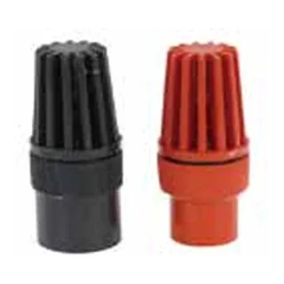
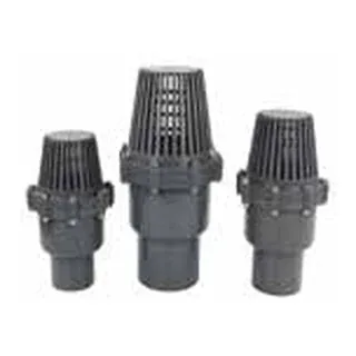
A foot valve is a check-valve arrangement at the submerged suction inlet, normally incorporating a screen. An inline check provides the non-return function within the pipe; screening remains a separate requirement. For a concrete product example, Val-Matic’s Sure Seal foot-valve documentation describes a check with basket screening and a priming application. Its construction and performance claims belong to that product, not to all foot valves or to NOVA.
Suction lift means the pump draws from a liquid level below it. Retaining liquid between starts can therefore matter to priming. Flooded suction supplies positive head from a liquid level above the pump, which changes that priming problem. Xylem’s e-XC instruction manual, section 5.2, distinguishes positive-head priming from suction-lift priming. This distinction explains why an arrangement chosen for an above-water lake pump cannot automatically be carried over to a below-tank pump.
| Pump and supply condition | Choose the permitted arrangement | What changes the answer |
|---|---|---|
| Non-self-priming pump on suction lift | Compare the pump-permitted foot valve with any documented inline-check and separate-screen alternative. | Preserve the required primed column; assess valve and screen losses for either option. |
| Flooded suction | Use the exact pump’s positive-head piping and priming requirements. | An above-water prime-retention argument alone does not justify an added suction check. |
| Self-priming pump | Use that model’s permitted intake, non-return and priming arrangement. | Self-priming alone neither requires a foot valve nor permits omitting all suction non-return hardware. |
This is an arrangement decision before it is a valve-type decision. NOVA’s guide to check-valve types for plastic water lines covers closure designs and line duties. Here, the question is narrower: can a proposed combination of position, screening and retained water serve this pump’s suction duty?
First distinguish a loss of prime from a valve-selection problem
Start with the supply condition and the observed state, not with a replacement valve. A pump on suction lift needs the water required by its permitted priming arrangement; a flooded-suction system starts with a different liquid boundary. If an otherwise permitted line repeatedly loses prime, the question is where water can leave or air can enter. Changing the check type does not establish that the suction pipe, joints or the check seat seal correctly. The Pentair guide identifies suction-line air leakage as a condition to eliminate; it does not identify every lost-prime event as a failed foot valve.
For a design review, mark the source liquid level, intake screen, each non-return boundary and pump on the same sketch. Then ask which section remains on the pump side of each closed check. That identifies what the valve can prevent from returning through it. It does not prove a real installation holds water: sealing, elevation and other boundaries still matter. Keep “this layout could retain the intended column” separate from “this installation has been verified airtight.” The first is a design inference; the second needs actual inspection or testing under the pump instructions.
Source and scope
An inline check can retain prime—but its location matters
The Pentair end-suction centrifugal pump owners guide, hosted as ADs101C203, identifies CJ103/EL103 and CJ101/EL101 series on its opening page. The captured document is marked 130441 D, copyright 2018. It describes the units as non-self-priming. Its suction-lift guidance, item 5 on printed page 7, offers a foot valve in the water or a check positioned as close to the water as possible to reduce priming time and help maintain prime. The same item requires a suction-line strainer for dirt and debris.
The location qualifier explains the exception. In normal suction flow, water moves from the source through the check toward the pump. When the check closes against reverse flow, it forms a retaining boundary for water on its pump side. A submerged foot valve places that boundary at the intake. A check farther along the suction pipe leaves a source-side length outside that boundary. Moving the check toward the pump makes that unretained length longer.
That does not mean every source-side pipe immediately empties: its elevations, air entry and other boundaries matter. It means the check alone does not prevent that length from draining back. For a conceptual comparison, assuming sound sealing and an otherwise suitable layout, a check at the pump can retain water locally while the upstream suction run can still lose water if air enters. A submerged foot valve instead opposes return through the inlet for the column above it. Neither arrangement compensates for leakage elsewhere.
Conceptual layouts, following flow toward the pump: water → foot valve with screen → suction pipe → pump; or water → separate screen → short source-side run → manufacturer-permitted inline check → suction pipe → pump. Moving the inline check beside the pump leaves most of the suction pipe on the source side of the closed check. These are explanations of retention boundaries, not installation drawings.
Xylem’s e-XC manual gives a different set of model-specific conditions. Its foot-valve guidance on printed pages 30–31 addresses static suction lift and specifies a flapper arrangement rather than a multiple-spring arrangement, sized to avoid excessive suction friction. For a suction check, it calls attention to added pressure drop, possible water hammer and exposure of the pump volute to discharge pressure. Those cautions do not create a universal suction-check ban; Pentair’s alternative does not cancel them. Each instruction governs its own covered equipment. Source: e-XC, section 4, foot valves and check valves.
Foot valve at the intake
With sound sealing, the inlet check opposes return through the intake for the column above it.
Permitted inline check close to water
A separate screen remains at the intake; only the pipe on the pump side of the check has that retaining boundary.
Inline check beside the pump
Most source-side pipe lies outside the check’s retaining boundary; local retention is not automatically whole-line prime retention.
Source and scope
Separate the retention decision from the operating decision
Consider two otherwise permitted candidates: a submerged screened foot valve and an inline check with a separate intake screen. Retention asks where each check closes against reverse flow. Operation asks what the whole path loses while water moves toward the pump. The same candidate must satisfy both questions. A layout that retains the right water can still add unacceptable resistance, while a low-loss candidate can still leave the water needed for priming outside its retaining boundary.
| Question | What establishes it | What cannot substitute |
|---|---|---|
| Retained water | Permitted location, intended column and sound sealing | Convenient service access alone |
| Operating suction duty | Actual valve, screen and pipe losses at the intended flow | Nominal size or cracking pressure alone |
| Acceptable candidate | Both functions within the exact pump requirements | A pass on only one question |
This separation also prevents a misleading ranking. If one supplier quotes a fully open loss coefficient and another quotes opening pressure, the values describe different conditions. There is no defensible “lower is better” comparison until the operating evidence is put on the same flow and opening-position basis. Keep each supplier’s definition and units with its data; the Val-Matic notation warning below is one reason a coefficient name alone is not enough.
Source and scope
Cracking pressure does not tell you the running loss
Cracking pressure concerns the differential needed to begin opening a check. Running loss concerns the pressure or head lost while water passes through the valve at the operating flow and actual opening position. That means two valves with the same nominal size and a quoted opening pressure cannot be ranked for running suction loss from those facts alone. The relevant evidence is their flow-loss data under the intended conditions, together with the screen’s loss. Val-Matic’s Engineering Manual glossary defines cracking pressure as the pressure required to lift the disc off its seat.
On the suction side, that resistance consumes available suction head. Xylem explicitly connects minimizing foot-valve and suction-line losses with maximizing NPSHA, the net positive suction head available to the pump. The comparison must include the complete inlet path: screen, valve or valves, pipe and fittings. A screen does not disappear from the hydraulic comparison just because it is separate from the inline check. Source: e-XC, printed page 31.
Source and scope
Low flow deserves particular attention. In Val-Matic’s Engineering Manual, section 4B, “Minimizing Energy Consumption Through Valve Selection,” printed pages 97–99, published head-loss characteristics presume optimum, fully open operation. The discussion explains that flow velocity can affect a swing check’s opening position; a partly open valve can have substantially more loss than its published fully open data implies. It therefore calls for a flow-coefficient-versus-velocity curve for that analysis.
This does not establish that absolute loss always rises when flow falls. Lower flow and a more restricted opening act together, so the actual curve is needed. The defensible conclusion is that a fully open coefficient can misrepresent low-flow service. The manual’s large-valve examples and velocity discussion are not a universal opening threshold for a small plastic suction valve. Section 4B also uses “Kv” for a dimensionless resistance coefficient; that notation must not be silently substituted for a differently defined supplier flow coefficient.
For selection, the useful comparison is loss at the lowest intended running flow and at duty flow, with the manufacturer’s opening-position limits, plus screen loss in the service condition being assessed. Those losses belong in the pump’s suction-head assessment against its NPSH requirement and the applicable margin. If the curves or pump requirement are missing, the hydraulic ranking remains unresolved. Once those inputs are available, exclude a candidate that fails the required suction margin even if it retains prime; among compliant arrangements, lower loss is a benefit only while the required priming function is preserved.
A second suction check must have a defined purpose
A foot valve plus a check near the pump is not automatically more reliable. In running flow, the losses of both checks and the screen contribute to the suction path. In the stopped arrangement, the two checks create separate retaining boundaries, making the intervening section’s filling, air release and drainage relevant. This is a conceptual consequence of their positions, not evidence that every two-check arrangement is prohibited.
A documented pump-system reason can justify two checks, but the review must explain what the second check achieves, how the sections remain fillable and serviceable, and whether the combined losses fit the required suction margin. Xylem’s e-XC cautions also make transient behavior and pressure exposure relevant. Forum agreement, disagreement or valve count alone cannot answer those questions. Without that purpose and assessment, “extra protection” is not a sufficient reason to add resistance.
How a loss comparison changes the decision
Build the comparison around the least-flow and duty-flow cases already required by the selection discussion. For each case, include the proposed screen condition and every check in the flow path. An easier-to-service screen that is separate from the check still contributes resistance. Likewise, adding a second check creates another component to include; its existence does not make the first valve’s loss disappear.
| Input | Comparison use | If it is missing |
|---|---|---|
| Lowest intended running flow | Check opening-position limits and applicable loss | Low-flow ranking remains unresolved |
| Duty flow | Compare complete valve and screen resistance | Do not rank from nominal diameter |
| Pump requirement and margin | Determine whether an arrangement meets suction duty | No acceptable hydraulic verdict |
| Second check, if proposed | Account for its function and added loss | Remove the unsupported extra-protection argument |
The condition that flips the result is not simply a lower catalogue number. First exclude arrangements outside the pump’s permission or required suction margin. Then compare service access and operating loss among the remaining candidates. A candidate with lower documented loss becomes useful only when it still preserves the necessary priming function. If those inputs are not available, identify the exact undecided comparison rather than declaring one valve family superior.
Source and scope
Access changes the maintenance tradeoff, not the hydraulic rule
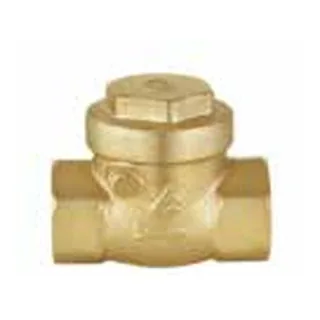
An accessible check can be easier to inspect or remove than a submerged foot valve. That benefit concerns the check itself. An inline alternative still leaves a screen at the intake to protect the suction path, so relocating the non-return hardware does not necessarily eliminate work at the lake. The screen and check have separate service needs when they are separate components.
Source and scope
| Component | Area relative to suction pipe (dimensionless) | Interpretation | Scope |
|---|---|---|---|
| Suction pipe | 1 | Reference | e-1510 reference |
| Foot-valve area | 1 | Minimum ≥1 | e-1510 requirement |
| Strainer area | 3 | Stated ratio 3 | e-1510 requirement |
Illustrative scenario, not a recorded customer case: suppose a lake intake is hard to reach but the above-ground section is removable. An accessible check is an attractive candidate if the exact pump permits it, the location retains the water required for priming, separate screening remains suitable, and the total running loss is acceptable. If the candidate sits near the pump and leaves a long unretained source-side run, access has improved while whole-line prime retention has not been established. No project dimensions or measured losses are assumed here.
The layout assessment also needs to account for how each section can be filled, drained and serviced, and whether the suction path remains airtight. Those are properties to resolve in an approved arrangement, not a reason to improvise submerged connections or a startup procedure. An above-ground valve with uncertain retention can exchange one maintenance difficulty for a priming difficulty. A less accessible foot valve may remain the defensible choice where it is the documented arrangement and its loss is acceptable. The Pentair guide’s priming section specifically identifies suction-line air leaks as a condition to eliminate.
Screen requirements themselves can be model-specific. The Bell & Gossett Series e-1510 IOM, P2001406 Revision 8, suction-piping checklist, specifies a foot-valve area at least equal to the suction-pipe area for an open system with suction lift. It also specifies a strainer area three times the pipe area. These are that manual’s conditions, not generic NOVA sizing rules. They illustrate why a valve’s thread size alone cannot establish suitability for a screened intake.
Accessible check, inaccessible screen: resolve both service tasks
The lake-service question contains two maintenance tasks that can be mistaken for one. Relocating the check may make the non-return mechanism accessible, but the separate intake screen can remain submerged. A proposal that only moves the check therefore needs a separate answer for inspecting, clearing and servicing that screen. It should also show how the intervening suction section can be filled and drained within the permitted arrangement.
A useful service comparison names the component, access method and retention consequence separately. “The check is removable above ground” is an access advantage. “The intended suction water is retained” is another conclusion, established from position and sealing. If a near-pump check leaves most of the source-side run outside its boundary, the proposal has resolved access to one component while leaving whole-line priming unresolved. The result can change when a pump-permitted close-to-water position and suitable screening are documented; it does not change merely because the valve has become easier to reach.
Source and scope
Require both retention and suction duty
First confirm that the exact pump manual permits the proposed valve position and separate screening. Then resolve these two independent conditions. Service access breaks a tie only after both are satisfied.
| Required water retained? | Suction duty met? | Verdict | What changes the result? |
|---|---|---|---|
| Yes, documented position/sealing | Yes, supported at operating flow | Candidate arrangement | Compare service access; preserve screening and exact manual conditions |
| No, intended column can drain | Yes | Hold; duty alone is insufficient | Resolve permitted location and retention before selection |
| Yes | No, losses exceed available margin | Reject this hydraulic selection | Redesign within pump instructions; reassess actual combined loss |
| Unknown | Unknown or unproved | Hold the comparison | Obtain location/priming evidence and actual valve/screen loss data |
Retention is established from the permitted layout and sealing boundary. Suction-duty assessment needs actual valve and screen losses at the required flow, together with the pump’s available/required suction margin. Nominal size or cracking pressure cannot stand in for those inputs. A manual prohibition excludes the arrangement even if these two checks look favorable.
Which arrangement is defensible for your pump?
Conclusion
Choose the pump-permitted arrangement that retains the intended water and meets the required suction duty. A submerged foot valve places the non-return boundary at the intake; a permitted inline check can be a candidate when its position and separate screen preserve the required function.
Compare actual operating loss before using access as a tie-breaker. If instructions, curves or the required pump margin are missing, state the unresolved decision; nominal size, opening pressure and an extra check cannot fill that evidence gap.
Frequently Asked Questions
Can an inline check replace the submerged foot valve?
Only where the exact pump permits that arrangement, with suitable location, separate screening and acceptable suction loss. Pentair’s cited close-to-water alternative applies to its covered pumps.
Should I add a second check for extra protection?
Only with a documented pump-system purpose and acceptable combined loss, filling, drainage and pressure behavior. Two checks alone do not establish greater reliability.
Will moving the check above ground remove all intake maintenance?
No; a separate submerged screen still needs service. Easier check access does not settle prime retention or suction duty.