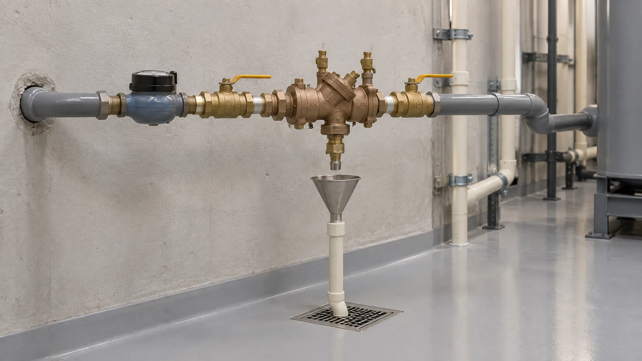
Check valve types differ in how they close, but the first choice is the line duty. A ball check or spring check provides automatic non-return action; a foot valve applies that action at a pump’s suction inlet to help retain prime. A handle-operated ball valve provides isolation. It does not become a check valve because both designs contain a ball.
Put the required function beside the valve symbol on the drawing. “Stop reverse flow when the pump stops” and “close the line for maintenance” describe different jobs. If the schedule says only ball valve, a supplier can reasonably quote manual isolation while the designer expects automatic closure. The material and end connections may match perfectly. The function will still be wrong.
University of Florida irrigation guidance separates on-off valves from check valves and identifies the foot valve’s role in retaining pump prime. Use that distinction before choosing a body material. A plastic line can need an isolation valve and a non-return valve in the same assembly; one label should not conceal both requirements.
A suction-line foot valve aims to keep water from draining out of the suction pipe when the pump is idle. A non-return valve elsewhere answers reverse flow at its own location. Mark suction or discharge on the enquiry rather than expecting the supplier to infer it from pipe size. Include the flow direction and where the valve sits relative to the pump and source.
Illustrative selection, applying the University of Florida duty distinction: a tank-fed pump needs suction-prime retention, a service branch needs manual isolation, and the discharge needs non-return review. Create separate schedule rows. These are design questions, not an IFANNova installation record or a complete pump-system design.
| Duty / design | What it does | Best for review | Evidence still needed |
|---|---|---|---|
| Ball check | Free ball lifts with forward flow and returns to its seat | Non-return duty where the exact model fits fluid and layout | Orientation, opening requirement, pressure-loss data, solids limits |
| Spring check | Spring-loaded element opens against spring force | Non-return duty needing a documented closing response | Cracking pressure, flow curve, wetted materials, permitted orientation |
| Foot valve | Non-return valve with suction-inlet strainer | Retaining prime in a pump suction line | Submerged installation, strainer selection and accessible cleaning |
| Ball isolation valve | Operator turns the closure element | Deliberate on/off isolation | Connection and duty ratings; not automatic reverse-flow closure |
For the suction row, shortlist a foot valve with strainer. Close it only when the proposed model’s submerged-installation instructions, wetted-material suitability and cleaning access match the intake drawing. For the service row, shortlist a manual ball isolation valve; confirm its end connections and removal arrangement. Its handle operation answers service isolation, not automatic pump-stop closure.
Keep the discharge row open: choose no ball or spring check merely from the suction and isolation catalogue listings. The designer must compare permitted orientation, opening differential, pressure loss and closure behavior against the discharge duty. A documented model match closes that row; an unverified “equivalent” leaves it on hold. Release each accepted row by drawing revision, without letting a confirmed foot valve approve the discharge choice.
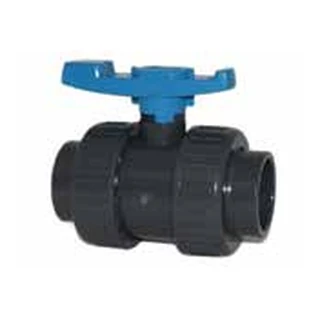
A ball check uses a freely moving ball that lifts under forward flow and returns to a seat. A spring check uses a spring-loaded closing element; forward pressure must overcome its opening resistance. Chemline’s thermoplastic check-valve guide describes both mechanisms and distinguishes their application considerations. Its recommendations concern the designs and product series it discusses, not every valve bearing the same type name.
Cracking pressure means the pressure difference needed to begin opening the valve. It is not the body’s pressure rating. A body rating cannot tell the designer whether the valve opens at the available forward differential or how much pressure it loses at the required flow. Ask for those records separately; choosing the largest rating printed on the body does not resolve the flow question.
Gravity and flow direction matter for a free-ball closure. Chemline generally recommends vertical installation for the ball checks described in its guide and describes horizontal or vertical installation for its spring designs. Treat those statements as reasons to check instructions, not permission to rotate an unknown model. The exact manufacturer drawing should name permitted mounting positions and flow direction.
Compare the pressure-loss curve at the intended flow, including any low-flow operating condition. Also ask whether the fluid carries suspended solids, and which internal materials contact it. A broad solids-handling description is not a debris-size limit. Spring material, seat material and body material all belong in the compatibility review; matching only the plastic body leaves part of the valve unreviewed.
Fast closure alone does not establish surge control for a pump system. Keep the valve’s closing behaviour and the system’s transient-pressure assessment as separate review items. If pump stopping or flow reversal drives the selection, carry that operating sequence into the design review. Avoid accepting an unsupported “no water hammer” promise in place of model data and system analysis.
Connection compatibility is another decision, not a diameter label. Use the pipe-sizing chart to distinguish the pipe specification from the valve’s mating dimensions, then compare the offered socket, spigot or thread drawing with the actual pipe. Confirm joint instructions for the material pair. Review the seat, seals and any spring against the fluid and temperature as well; a compatible body cannot approve a different wetted component.
For an alternative joint, keep the selection on hold until the supplier identifies the mating standard and applicable assembly instructions. A material name shared by pipe and valve does not resolve a socket or thread mismatch. Record the accepted connection in the schedule, so purchasing cannot substitute an apparently similar end without reopening that documented interface for technical review.
For maintenance, identify what the technician can remove and how the line will be isolated first. A union connection can make removal possible, but it does not supply safe isolation by itself. Show the required clearance and a deliberate means of shutting off the line in the maintenance arrangement.
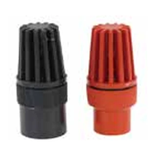
A foot valve combines a non-return function with a strainer at the suction inlet. Chemline describes installation at the end of a suction line, usually submerged in the source, to help retain prime when the pump shuts down. The University of Florida guide identifies the same retention function. The purpose is specific: stop the suction line from emptying back into the source.
That makes the installation arrangement part of the selection. Identify the source, inlet position and access for inspection. Ask the supplier to confirm the proposed submerged arrangement and the pump designer to review the complete suction path. A foot valve cannot correct every reason a pump loses prime; the rest of the suction system still needs review.
The strainer limits entry of larger debris, but it also creates a maintenance task. Include a way to inspect and clean it without treating removal as an afterthought. A drawing that shows the valve at the bottom of a tank should also show how the maintenance team reaches it. A replaceable component provides little practical benefit if the installed arrangement prevents access.
Do not substitute a plain non-return valve solely because its pipe connection fits. That could remove the inlet strainer from the design. Do not substitute a manual ball valve either: an open isolation valve will not close automatically when the pump stops. Confirm the non-return action and the strainer as separate requirements in the foot-valve line item.
For replacement, send the existing model and intake drawing with flow direction and access constraints. Match the proposed strainer and installation instructions to those conditions, rather than accepting a similar catalogue photograph.
Give each valve line a function, location and exact connection description. Add the fluid, operating temperature, flow range, available opening differential and allowable pressure loss from the design. Leave no invented “typical” values in those fields. If the design team has not supplied an input, identify it as unresolved; the supplier should not silently select a value on your behalf.
Require the proposed model to answer orientation, wetted materials, connection dimensions and maintenance access. For a check valve, request its cracking-pressure record and pressure-loss information. For a foot valve, add the strainer and submerged-installation details. For an isolation valve, state the on-off task. These fields let the reviewer compare function and service instead of choosing a part on diameter alone.
The IFANNova UPVC valve catalogue lists standard, single-union and double-union ball valves as well as foot valves. Here, union describes a connection arrangement that can support removal; it does not establish automatic non-return action. The catalogue does not establish an IFANNova spring-check line, and this explanation should not be read as an offer of one.
The trade-off is between a design that answers the duty and a model that can be verified for the actual line. A ball check may suit a gravity-dependent arrangement; a spring design may answer a different opening and closure requirement. A foot valve targets suction retention. Select only after the exact model’s data supports the proposed position, fluid and flow conditions.
For contractors and procurement teams checking isolation or suction-foot-valve availability, compare the listed valve range with your duty schedule. Keep an unconfirmed check-valve design as an open technical item. A catalogue connection that matches your pipe is a starting point; a documented function match is the release decision.
Use a response column labelled “confirmed model or exception.” A supplier naming a different closure design should state the reason and submit its evidence against the same duty inputs. That keeps an alternative reviewable. Record every approved substitution against its drawing. A response saying only “equivalent” conceals the opening requirement, internal materials and permitted position, so it cannot close the technical enquiry.
No. A manual ball valve provides deliberate on-off isolation. A ball check uses a moving ball for automatic non-return action. Schedule the function explicitly.
Use the exact model’s installation instructions. Chemline describes different orientation considerations for its ball and spring designs; these do not authorize every model or mounting position.
Its non-return action helps retain suction-line water when the pump stops. Its inlet strainer also limits larger debris entering the line; verify the installation and cleaning access.
No. Body pressure rating, cracking pressure and pressure loss at flow are separate selection inputs. Request the relevant model data for each.
The cited catalogue establishes ball-valve and foot-valve listings. It does not establish an IFANNova spring-check line; availability needs confirmation.