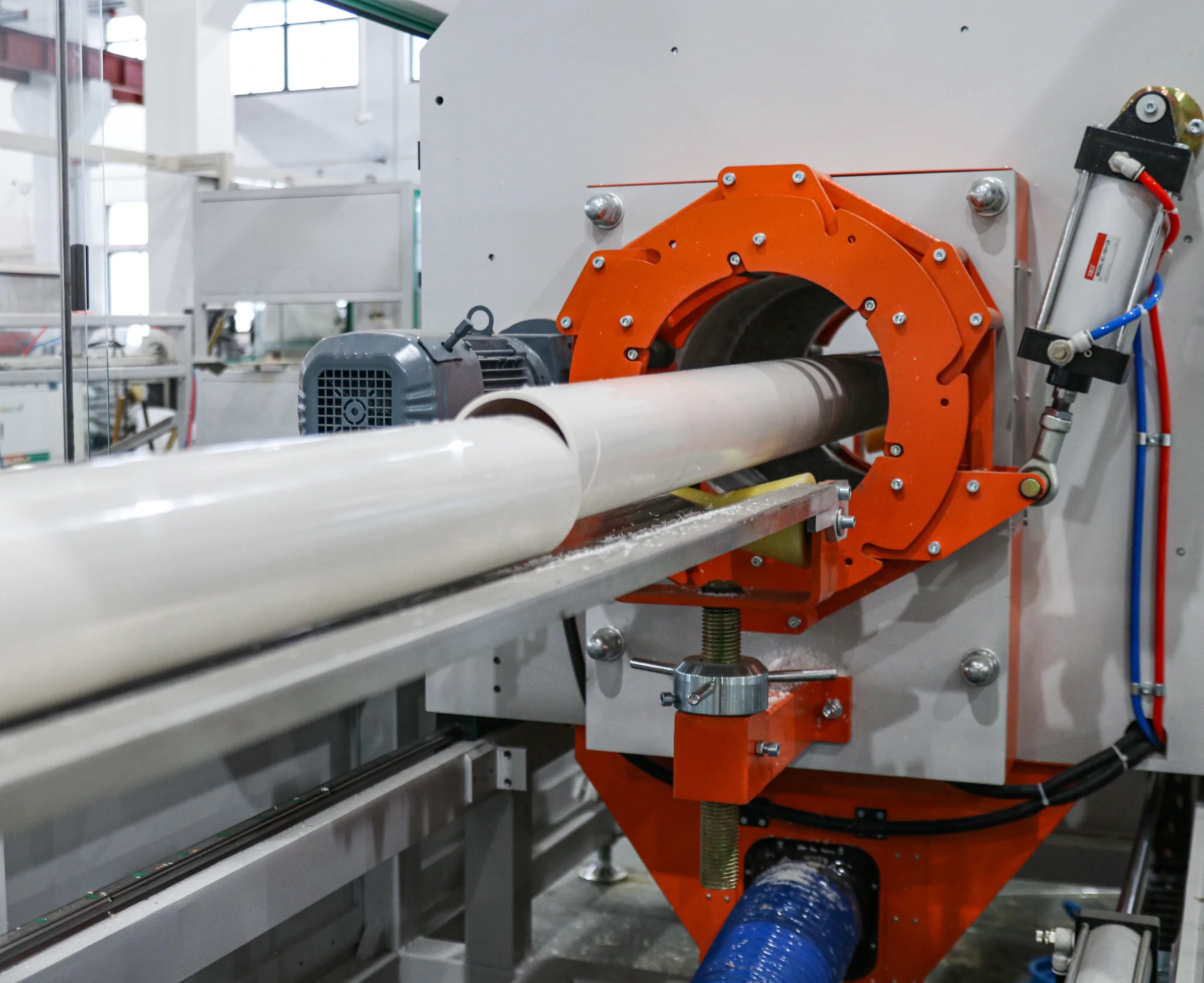
Most fittings guides sort parts by shape: elbow, tee, reducer, coupling. That shape-based grouping is the right one for a pressure system — we use it ourselves in the guide to types of pipe fittings — because there the fitting’s only job is to get water round a corner without leaking. It falls apart on a drainage system, because the pipe is not full, the flow is not steady, and the air inside the pipe matters as much as the water.
A gravity drainage stack is a machine for moving two things at once — wastewater downward and air both ways. When a slug of water falls down a stack it drags air with it, creating suction behind it and compression ahead of it. Every fitting on a drainage line is either helping manage that or making it worse. A trap that gets sucked dry stops being a trap. A branch connected in the wrong place gets its seal pulled out by the neighbouring appliance. An access point you did not fit is a wall you will open later.
So this list is organised by function in the air-and-water system, not by shape. Four families: the trap, the access fitting, the ventilation fitting, and the reducer. For each one — what it physically does, where it goes, the clause that governs it where a clause exists, and where our own 902 pipe and 1902 fitting range does and does not reach.
One thing to fix at the top, because everything below depends on it. Our PVC 902 drainage pipe and fittings range is non-pressure (per our catalogue): 902 pipe runs Φ32–110 mm and the matching 1902 fittings run Φ32–160 mm. It is a gravity sanitary and drainage system. Nothing on this page should be read as a recommendation to use it on a pressurised line, and where a required part sits outside that envelope we say so rather than steering you toward a substitute.
Every other fitting in a drainage system is trying to get water out. The trap is the one part deliberately designed to keep some.
BS EN 12056-2:2000 defines it at clause 3.4.4 as a “device that prevents the passage of foul air by means of water seal.” The seal is the working part, and it gets its own definition at clause 3.4.5 — the depth of water seal (H) is “the depth of water which would have to be removed from a fully charged trap before gases and odours at atmospheric pressure could pass through the trap.” That phrasing is worth reading twice. The seal is not a lid. It is a measured column of water, and it is defined by how much of it you would have to lose before the system stops working.
The normative body of BS EN 12056-2:2000 sets the European baseline at clause 5.4: “The depth of water seal (H) shall be not less than 50 mm.” No appliance-specific exceptions appear in the normative text. That is the number most suppliers quote, and on its own it is genuinely misleading for a UK project, because the same standard’s UK National Annex overrides it upward for most appliances.
Annex ND.2.2 of the same document is appliance-dependent, not flat. Traps with outlets up to and including DN 50 should have a minimum water seal of 50 mm on baths and showers, provided they are fitted with flush-grated wastes without plugs on spray-tap basins — and then the annex says plainly that “75 mm trap seals should be used with all other appliances.” Traps with outlets over DN 50 should have a minimum seal of 50 mm. Traps on flat-bottomed appliances with trailing waste discharge, discharging to a gully with a grating, may have a reduced seal of not less than 38 mm.
UK Approved Document H (2015) Table 1 lands in the same place from the regulatory side, and its detail is the reason a blanket rule fails:
| Appliance | Min. trap diameter | Min. seal depth |
|---|---|---|
| Washbasin, bidet | 32 mm | 75 mm |
| Sink, washing machine, dishwashing machine, food waste disposal unit, urinal bowl | 40 mm | 75 mm |
| Bath, shower | 40 mm | 50 mm |
| WC pan, outlet < 80 mm | 75 mm | 50 mm |
| WC pan, outlet > 80 mm | 100 mm | 50 mm |
Source: UK Building Regulations Approved Document H (2015), H1 Sanitary Pipework, Table 1.
Note the shape of that table. A WC pan — the appliance carrying the heaviest foul load — needs only a 50 mm seal, while a washbasin needs 75 mm. Anyone repeating “all traps need 75 mm” has the code backwards on the very appliance that matters most. The reason is physical, not arbitrary: a WC pan discharges a large volume through a short, wide outlet and is hard to siphon, whereas a small basin with a long thin waste is exactly the geometry that empties its own trap.
Approved Document H attaches three footnotes to that table, and they are the only permitted reductions: seal may drop to 50 mm only with flush-grated wastes without plugs on spray-tap basins (footnote 1); where the listed appliances discharge directly to a gully the seal may reduce to not less than 38 mm (footnote 2); and traps on flat-bottom appliances with trailing waste discharge, going to a gully with a grating, may have a reduced seal of not less than 38 mm (footnote 3). Outside those cases, the table value stands.
There are two seal numbers in these documents and they measure different things. The 50/75 mm figure is the static seal — what the trap holds when it is full and undisturbed. The second figure is what must survive the system doing its worst.
Approved Document H para 1.3 states it as a working requirement: “All points of discharge into the system should be fitted with a trap (e.g. a water seal trap) to prevent foul air from the system entering the building. Under working and test conditions traps should retain a minimum seal of 25mm of water or equivalent.” BS EN 12056-2:2000 Annex NG.3.2.1 sets the same threshold as a test protocol: “After each test a minimum of 25 mm of water seal should be retained in every trap. Each test should be repeated at least three times, the trap or traps being recharged before each test.”
In our experience reading enquiry specifications, this is where drainage schedules most often go wrong — a spec writes “25 mm seal” against a basin trap, having taken the residual figure for the product figure. They are not interchangeable. You buy a 75 mm trap so that after siphonage you still have 25 mm. Buying a 25 mm trap leaves you nothing to lose.
If you are specifying for a market on the International Plumbing Code rather than the European standards, the number changes and so does the shape of the rule. IPC Section 1002.4 requires that “Each fixture trap shall have a liquid seal of not less than 2 inches (51 mm) and not more than 4 inches (102 mm), or deeper for special designs relating to accessible fixtures.”
The significant difference is not the 51 mm, which is close enough to the European 50 mm. It is the maximum. EN 12056-2 imposes no upper limit on seal depth; the IPC does. A deeper-than-4-inch seal is not a bonus under the IPC — it is a non-compliance, on the reasoning that an over-deep seal retains solids. A trap that satisfies the UK’s 75 mm requirement sits comfortably inside the IPC band, but the two codes are not simply “more or less the same,” and a schedule written for one market should be re-read before being used in the other. We should be explicit about our sourcing here: this IPC figure is supported by ASPE and by UpCodes reproductions of adopting jurisdictions; the ICC’s own pages were not accessible to us directly.
BS EN 12056-2:2000 Annex NA.2.7 describes a resealing trap as a trap with a physical minimum depth of water seal of 50 mm that retains sufficient liquid after siphonage to ensure a reduced seal of at least 25 mm depth is retained. It is a named product type with its own behaviour. Its reduced-seal allowance belongs to that product and does not transfer to an ordinary tubular trap — which is how it sometimes gets used in argument on site, as a reason a shallow seal “should be fine.”
Straight answer: appliance traps are a sanitaryware-adjacent product line and are not something we list. Our PVC 902 drainage range covers Φ32–110 mm non-pressure pipe and the Φ32–160 mm 1902 fitting series — elbows, 45° elbows, tees, reduced tees, Y-tees, reduced Y-tees, sweep tees, double Y-tees, sockets, invert reducers, reducing plugs, caps, plugs, pipe clips and solvent cement (per our catalogue). That is the carrier system downstream of the trap. The Φ32 and Φ40 end of the range is the size band that receives basin and sink trap outlets; Φ110 is the stack and WC band. If your enquiry needs the traps themselves supplied as part of one matched package, tell us and we will say what we can and cannot include rather than quoting around it.
For product-standard traceability, Approved Document H Table 4 lists BS EN 274 and BS 3943 as the material standards for traps — worth naming in a tender document, because “trap” alone is not a specification.
The access fitting is the one that costs nothing at first fix and a great deal at year three. It has no hydraulic function whatsoever. Its entire purpose is to let a rod or a jetting hose reach a blockage without demolition.
Approved Document H para 1.6 sets the rule as a pairing with the trap: “If a trap forms part of an appliance the appliance should be removable. All other traps should be fitted directly after the appliance and should be removable or be fitted with a cleaning eye.” Two acceptable answers, then — the trap comes off, or the trap has an eye in it. Not neither.
Para 1.25 extends that to the pipe itself: rodding points should be provided to give access to any lengths of discharge pipe which cannot be reached by removing traps or appliances with internal traps. The design test is simple and worth applying to a drawing before it is issued. Trace every metre of discharge pipe. For each metre, name the opening a rod enters through. Any metre with no answer needs a rodding point.
Where a floor gully is in the system, EN 1253-1:2015 clause 4.2.1 sizes the opening: cleaning openings of not less than 32 mm clear diameter for gullies DN 110 or below, and not less than 50 mm for DN 125 to DN 200. That is a clear-diameter requirement, which is a different measurement from the nominal size of the cover — a distinction worth checking on a submittal.
Our 1902 series includes caps and sockets, which are the parts a rodding arrangement is built from in a solvent-welded PVC system (per our catalogue). Whether a given project’s access detail is best served by a dedicated access fitting or by a capped branch is a design decision we are not going to make from a distance. What we can do is tell you which of our listed items exist in your diameter. We have not found a citable published figure for the frequency at which access points should be spaced along a horizontal drainage branch in the documents checked for this article, so we are not going to invent one — the governing requirement we can cite is the reachability test in para 1.25, not a spacing interval.
This is the family most commonly value-engineered out of a drainage design by someone who has not read why it is there. So start with the mechanism.
BS EN 12056-2:2000 Annex NC.2.1 names two loss mechanisms. Self-siphonage occurs when the branch discharge pipe from an appliance flows full bore — the moving slug of water acts as a piston and pulls the appliance’s own trap seal out behind it. Induced siphonage occurs on a non-discharging appliance when a shared branch flows full bore or when stack flow creates negative pressure — one fixture’s discharge empties another fixture’s trap.
Annex NC.2.2 adds the stack-geometry effects, and the second half of it is the one people forget: “Suction can occur below discharging branch connections and offsets, causing water seal loss by induced siphonage… Back pressures or positive pressures can occur above offsets and bends in stacks, causing foul air to be blown through the trap water seal and sometimes seal loss.”
Foul air blown through a full seal. That is the failure mode that produces a smell complaint in a building where every trap is correctly sized and full of water — and it is a positive-pressure event, which is why it cannot be solved by any device that only admits air.
| Term | EN 12056-2:2000 definition (clause) |
|---|---|
| Ventilating pipe | “pipe provided to limit the pressure fluctuations within the discharge pipe system” (3.3.1) |
| Branch ventilating pipe | “ventilating pipe connected to a branch discharge pipe” (3.3.2) |
| Stack vent | “extension of a vertical discharge pipe above the highest branch discharge pipe connection that terminates in an end, open to the atmosphere” (3.3.3) |
| Ventilating stack | “Main vertical ventilating pipe, connected to a discharge stack, to limit pressure fluctuations within the discharge stack” (3.3.4) |
| Air admittance valve | “valve that allows air to enter the system but not to escape in order to limit pressure fluctuations within the sanitary pipework” (3.3.5) |
Read the AAV definition against the positive-pressure failure quoted above. The standard’s own wording — air in but not out — is the reason an AAV is not a universal substitute for an open vent. It answers suction. It cannot relieve back pressure.
EN 12056-2 clause 4.3.1 describes the primary ventilated system: “Control of pressure in the discharge stack is achieved by air flow in the discharge stack and the stack vent… Alternatively, air admittance valves may be used.” Clause 4.3.2 describes the secondary ventilated system: “Control of pressure in the discharge stack is achieved by use of separate ventilating stacks and/or secondary branch ventilating pipes in connection with stack vents.”
In commercial terms this is the single biggest fork in a drainage fittings take-off. A secondary ventilated system means a second vertical pipe run and a second set of fittings for it — roughly a doubling of the vertical element of the schedule. When a quotation comparison shows one bidder dramatically cheaper on a multi-storey job, this is the first line to check.
Approved Document H para 1.19 gives the exemption: “separate ventilation will not be needed to prevent the water seals in traps from being lost by pressures which can develop in the system if the length and slope of the branch discharge pipes do not exceed those shown in Table 2 or Diagram 3.” Para 1.20 gives the consequence if they are exceeded — the branch “should be ventilated by a branch ventilating pipe to external air, to a ventilating stack (ventilated branch system) or internally by use of an air admittance valve.”
AD H Table 2 gives the permitted length-and-gradient pairs, and for a washbasin or bidet on a 30 mm branch the permitted length shrinks as the gradient steepens: 1.7 m at a gradient of 18 to 22 mm fall per metre, 1.1 m at 18 to 44, and 0.7 m at 18 to 87. A 40 mm branch is permitted 3.0 m and a 50 mm branch 4.0 m, both at 18 to 44. Check the published table for appliances other than the washbasin, bidet and WC rows before you commit a layout.
Two figures from AD H para 1.22 that decide whether a branch vent works. It “should be connected to the discharge pipe within 750mm of the trap and should connect to the ventilating stack or the stack vent, above the highest ‘spillover’ level of the appliances served.”
Both halves matter. The 750 mm is a proximity rule — connect further away and the vent is no longer breaking the siphon where the siphon forms. The spillover rule is a flooding rule — connect the vent below the level at which an appliance overflows and the vent becomes a discharge route.
Para 1.24 sizes it: branch ventilating pipes serving one appliance should be at least 25 mm diameter, or at least 32 mm where the branch is longer than 15 m or has more than 5 bends. Note what triggers the upsize — not the appliance, but the run’s length and bend count.
AD H para 1.29 is unambiguous that this is not optional: “To prevent water seals in the traps from being lost by pressures which can develop in the system, discharge stacks should be ventilated. Discharge stacks connected to drains liable to surcharging or near an intercepting trap require ventilating pipes of not less than 50mm diameter connected to the base of the stack above the likely flood level.”
Para 1.32 covers the dry portion: “stack ventilation pipes (the dry part above the highest branch) may be reduced in size in one and two storey houses, but should be not less than 75mm.” The permission is conditional — one- and two-storey houses, not a general licence to shrink the vent.
The termination rule is para 1.31: “Ventilating pipes open to outside air should finish at least 900mm above any opening into the building within 3m and should be finished with a wire cage or other perforated cover… which does not restrict the flow of air.” Para 1.23 applies the same 900 mm / 3 m geometry to branch ventilating pipes running direct to outside air. In rodent-problem areas the cover should be metallic. This clause quietly kills a lot of neat-looking elevations, because a vent terminal that clears the roof but sits 2 m from a rooflight or an opening window is not compliant.
AD H para 1.33: “Ventilated discharge stacks may be terminated inside a building when fitted with air admittance valves complying with BS EN 12380:2002. Where these valves are used they should not adversely affect the amount of ventilation necessary for the below ground [drainage].” EN 12056-2 clause 5.7 likewise requires AAVs used to vent drainage systems to comply with prEN 12380.
So the AAV is a legitimate, code-recognised device — with a product standard attached, a condition about below-ground ventilation, and explicit limits: the same paragraph requires AAVs to sit in areas with adequate ventilation, to be accessible for maintenance and removable for clearing blockages, and states they should not be used outside buildings or in dust laden atmospheres. What it is not is a free deletion of the vent stack, for the reason the standard’s own definition gives: it admits air only.
This is the family where we have to be most direct about our envelope. Our 902 PVC drainage system is non-pressure (per our catalogue), with pipe Φ32–110 mm and 1902 fittings Φ32–160 mm. Vertical stacks and vent stacks in that band are within our size range on the pipe side, and the 1902 series supplies the elbows, tees, Y-tees, sweep tees, double Y-tees, sockets and reducers a vented layout is assembled from. Air admittance valves themselves, and BS EN 12380 certification for them, are not in our catalogue — we are not going to imply otherwise. Where a project’s stack or vent exceeds Φ160, or where the below-ground drain runs at DN 200 and above, that is outside what we manufacture and we will say so at enquiry stage rather than after an order.
A reducer in a pressure system is a size change. In a drainage system it is a size change with a rule attached about which way it may point.
AD H para 1.28 states it directly for stacks: they “should not reduce in the direction of flow.” Then the minimum sizes: stacks serving urinals not less than 50 mm; stacks serving closets with outlets less than 80 mm not less than 75 mm; stacks serving closets with outlets greater than 80 mm not less than 100 mm. And the governing cross-check — the internal diameter of the stack should be not less than that of the largest trap or branch discharge pipe connected to it. If you are converting between DN, OD and the nominal sizes a schedule mixes freely, our pipe sizing charts set out which figure each system is actually measuring.
| Stack serves | Minimum stack size |
|---|---|
| Urinals | 50 mm |
| Closets with outlet < 80 mm | 75 mm |
| Closets with outlet > 80 mm | 100 mm |
| Any stack, additional rule | Not less than the largest trap or branch discharge pipe connected |
Source: UK Building Regulations Approved Document H (2015), para 1.28.
That last row is the one that catches take-offs. A stack can satisfy the appliance-based minimum and still be undersized because someone connected a larger branch to it. The stack size is the maximum of the two tests, not the appliance table alone.
The practical consequence for a fittings order: on a drainage stack, a reducer is a fitting you install pointing up the flow, expanding as water descends — never the reverse. A reducer specified with its large end down on a vertical stack is a compliance failure regardless of how neatly it fits.
Reducers are a listed part of the 1902 series (per our catalogue), and the 902 pipe range’s Φ32–110 span covers the 50, 75, 100 and 110 mm sizes named in the paragraph above. Beyond Φ160 we do not manufacture, so a DN 200 or larger below-ground main is not something we can supply and we will not offer a substitute that pretends otherwise.
These are not usually filed as “drainage fittings” but they belong here, because in both cases the geometry of a fitting is doing a pressure-management job.
AD H para 1.26: “The bend at the foot of the stack should have as large a radius as possible and at least 200mm at the centre line.” That is a radius specification on a bend — which means “a 110 mm bend” is an incomplete description for this position. The bend where the vertical stack turns horizontal is where descending water decelerates hardest and where the compression that blows out seals higher up is generated. A tight elbow there creates the pressure that a vent then has to relieve.
AD H para 1.27: offsets in the “wet” portion of the stack should be avoided. Where they are unavoidable, in a building of not more than three storeys there should be no branch connection within 750 mm of the offset. In a building over three storeys a ventilation stack may be needed with connections above and below the offset. That is a direct link between an architectural decision and a fittings schedule — an offset added late to route around a structural element can convert a primary ventilated system into one needing a ventilating stack.
AD H para 1.30 sets three simultaneous conditions for a stub stack: it connects into a ventilated discharge stack, or into a ventilated drain not subject to surcharging; no connected WC has a floor level more than 1.3 m above the invert of the connection or drain; and no other branch into the stub stack has a centreline more than 2 m above that invert. All three, not any one. This is a commonly mis-stated arrangement, usually by dropping the 1.3 m WC condition and keeping only the 2 m figure.
“PVC drainage fittings” is not a specification and will not protect a tender. Approved Document H Table 4 names the product standard per material, and these are the strings that belong in a submittal:
| Material | Product standard (AD H Table 4) |
|---|---|
| PVC-U | BS EN 1329 |
| Polypropylene (PP) | BS EN 1451 |
| ABS | BS EN 1455 |
| Polyethylene (PE) | BS EN 1519 |
| Styrene copolymer blends (PVC+SAN) | BS EN 1565 |
| PVC-C | BS EN 1566 |
| Cast iron | BS 416, BS EN 877 |
| Copper | BS EN 1254, BS EN 1057 |
| Traps | BS EN 274, BS 3943 |
Source: UK Building Regulations Approved Document H (2015), Table 4, “Materials for sanitary pipework”.
On our own certification position, we should state it exactly as it stands: IFANNova holds SKZ, CE, WRAS, DVGW, SGS, ISO 9001 and ISO 14001 (per our catalogue). Certificate numbers are Coming soon. Where a tender requires a specific certificate number against a specific product standard for the 902 drainage range, ask us for it at enquiry and we will tell you what we can evidence rather than listing a standard we cannot document.
| Fitting | What it does | Where it goes | Governing figure | In our 902/1902 range? |
|---|---|---|---|---|
| Trap | Holds a water seal against foul air | Directly after the appliance | 50 mm EN baseline; 75 mm for most appliances per UK NA / AD H Table 1; 25 mm residual after test | No — traps are not a listed line; the 902/1902 system is the carrier downstream |
| Cleaning eye / rodding point | Rod and jetting access | On the trap, or anywhere a rod cannot otherwise reach | AD H 1.6 and 1.25 (reachability, not spacing); EN 1253-1 4.2.1 gully openings 32 mm / 50 mm clear | Partly — sockets and caps listed; access detail is project-specific |
| Branch ventilating pipe | Breaks siphonage at the appliance | Within 750 mm of the trap; connects above highest spillover level | AD H 1.22, 1.24 — min. 25 mm; 32 mm if >15 m or >5 bends | Pipe and fittings within Φ32–160, non-pressure |
| Stack vent / ventilating stack | Limits pressure fluctuation in the stack | Above the highest branch connection; terminal in open air | AD H 1.29, 1.31, 1.32 — 50 mm at stack base where surcharge risk; dry stack not less than 75 mm; terminal 900 mm above openings within 3 m | Pipe and fittings within Φ32–160, non-pressure |
| Air admittance valve | Admits air only; relieves suction, not back pressure | Internal stack termination, conditions applying | AD H 1.33 — BS EN 12380:2002 | No — not a catalogue item |
| Reducer | Diameter change | Never reducing in the direction of flow on a stack | AD H 1.28 — 50 / 75 / 100 mm minima, and not less than the largest connected branch | Yes — listed in the 1902 series, Φ32–160 (902 pipe to Φ110) |
| Long-radius bend at stack foot | Reduces compression at the base | Vertical-to-horizontal transition | AD H 1.26 — at least 200 mm centreline radius | Elbows and sweep fittings listed; confirm centreline radius at enquiry |
Two gaps, stated so you know where this page stops, and two items we were able to source after all:
We would rather have a shorter page that holds up than a longer one that does not.
An honest summary, because a fittings guide from a supplier is only useful if the supply boundary is visible.
What we manufacture for drainage: the PVC 902 pipe range, Φ32–110 mm, non-pressure, plus the Φ32–160 mm 1902 fitting series — elbows, 45° elbows, tees, reduced tees, Y-tees, reduced Y-tees, sweep tees, double Y-tees, sockets, invert reducers, reducing plugs, caps, plugs, pipe clips and solvent cement in one matched matrix (per our catalogue). That covers appliance branch sizes through to a Φ110 stack and Φ160 collector, made in the same facility as our UPVC / CPVC 806 pressure range (1806 series, 203 items) so a project needing both supply and drainage does not have to reconcile two vendors’ sockets.
What we do not supply, plainly: appliance traps; air admittance valves and their EN 12380 certification; anything above Φ160 on the drainage side; and on the pressure side our ceiling is Φ110 with PPR at 20/25/32 mm only, so we cannot serve a DN 150–400 main. If your drainage scope includes below-ground mains at DN 200 and above, part of that scope is not ours and we will tell you which part at the enquiry, not after the order.
Commercial terms: MOQ, FOB pricing and lead times are Coming soon. Certificate numbers for SKZ, CE, WRAS, DVGW, SGS, ISO 9001 and ISO 14001 are Coming soon. We would rather write that than publish a number we cannot stand behind.
IFANNova is a French brand of French-designed, European-standard piping, manufactured in our own facility in Zhuji, Zhejiang, China. Product is not represented as made in France.
The most useful thing you can send is a schedule that names each item by diameter and function in the system — “Φ110 sweep tee, stack branch connection” rather than “tee.” Where a line is a trap, a vent valve or a size above Φ160, we will mark it as outside our range rather than quoting around it.
Send your drainage schedule for a line-by-line supply check
A specification-led uPVC drainage guide: EN 1329 above ground vs EN 1401 below ground, 75/100 mm service minimums, Approved Document H gradients (1:40, 1:80, 1:150)…
An irrigation network is three pressure tiers, not one.
Socket fusion parameters for PP-R by diameter: heater at 260 ± 10 °C, heating 5–60 s, change-over max 4–10 s, insertion depth 14.5–40 mm.
