Our catalogue states a wall thickness for every diameter we make. This page puts the whole table in front of you, marks the ceiling at Φ110, and flags the standard printed on our pipe that does not belong there.
Search for an HDPE pipe diameter chart and you will get a hundred pages of tables running from 20 mm to 1600 mm, each one with a complete wall thickness column, an inside diameter column and a kg/m column, all filled in to one decimal place. They look authoritative. Almost none of them tell you where a single number came from, and a large share of them were generated by feeding a diameter list through the SDR formula and printing the output.
That is a defensible thing to do if you label it. It is not defensible if you label the output “HDPE pipe specifications” and let a buyer put it on a purchase order. A calculated wall thickness is a geometric consequence of an assumed ratio. A manufactured wall thickness is a measured property of a specific extrusion line running a specific compound to a specific tolerance. They are not the same kind of fact, and this page keeps them in separate columns.
So here is the deal for this page. Our HDPE pressure line runs Φ20 × 2.3 to Φ110 × 10 (per our catalogue), and our catalogue carries a per-size wall thickness for all nine diameters in between — not an endpoint pair, the whole column. Section 1 reproduces it row for row. Every wall figure on this page is transcribed from that table; nothing is computed from an SDR ratio and relabelled as product data. Where we genuinely do not hold a figure — per-size SDR designation, resin grade, confirmed shipping weights — we say so in those words rather than filling the cell.
This page is the data layer. If you need the concepts underneath it — what DN means and why it does not convert to NPS, how SDR relates to pressure, why PN has two different definitions, how temperature derates a pressure class — those are settled in full on our pipe sizing charts reference. This page assumes you already know them and gets on with the numbers.
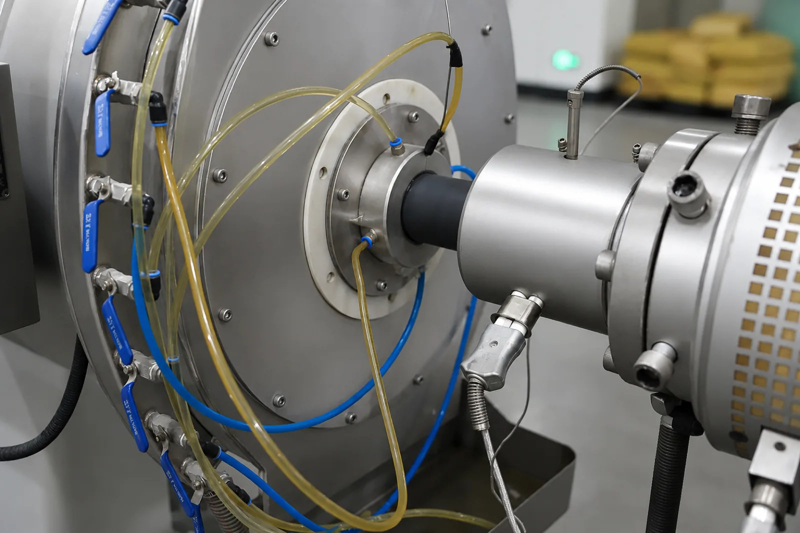
Here is the table, in full, as our catalogue prints it. Nine diameters, nine walls, one pressure class. This is the reference the rest of the page works from.
| Designation | Nominal OD dn (mm) | Wall e (mm) | Source of the wall figure | Class |
|---|---|---|---|---|
| Φ20 × 2.3 | 20 | 2.3 | Catalogue-stated (per our catalogue) | PN16 |
| Φ25 × 2.3 | 25 | 2.3 | Catalogue-stated (per our catalogue) | PN16 |
| Φ32 × 3.0 | 32 | 3.0 | Catalogue-stated (per our catalogue) | PN16 |
| Φ40 × 3.7 | 40 | 3.7 | Catalogue-stated (per our catalogue) | PN16 |
| Φ50 × 4.6 | 50 | 4.6 | Catalogue-stated (per our catalogue) | PN16 |
| Φ63 × 5.8 | 63 | 5.8 | Catalogue-stated (per our catalogue) | PN16 |
| Φ75 × 6.8 | 75 | 6.8 | Catalogue-stated (per our catalogue) | PN16 |
| Φ90 × 8.2 | 90 | 8.2 | Catalogue-stated (per our catalogue) | PN16 |
| Φ110 × 10 | 110 | 10 | Catalogue-stated (per our catalogue) | PN16 |
Nine rows, no gaps, no cell that says “enquire”. If you came here for a wall thickness against a diameter, you already have it and you can stop reading. The rest of this page is about the two things the table does not tell you: where the range ends, and what to be careful about when you compare this table against a chart from somewhere else.
One observation you can make from the column without any formula at all: the wall grows faster than the diameter. From 20 mm to 110 mm the diameter multiplies by 5.5, while the wall goes from 2.3 mm to 10 mm, a multiple of 4.35. The ratio dn/e is 8.7 at the bottom of the range and 11.0 at the top, and it does not move monotonically in between — Φ20 and Φ25 share a 2.3 mm wall, so the ratio jumps from 8.7 to 10.9 across a single size step, then settles back to 10.7 at Φ32 and drifts up through 10.9 at Φ63 to 11.0 at Φ110. A real production line is not a single SDR sweep. Small diameters carry proportionally thicker walls for handling, installation and minimum-extrudable-wall reasons that have nothing to do with hoop stress.
That is worth stating because it is exactly what you would have got wrong by computing the middle instead of reading it. Take the Φ110 ratio of 11.0 and apply it downward and you get 1.82 mm at Φ20, against the catalogue’s 2.3 mm — about 21% low. The point is not that we refused to do that arithmetic; it is that the arithmetic gives a different answer from the product, and only the printed table tells you which one goes on a purchase order.
Our HDPE line is metric OD-designated, which per ISO 161-1:2018 means the number on the pipe is the nominal outside diameter dn, defined in that standard as “the specified outside diameter, assigned to a nominal size DN” and, for metric pipes, as “the minimum mean outside diameter dem,min specified in the applicable pipe standard” (ISO 161-1:2018, Clause 3.1.2, Note 2). Φ110 means the mean outside diameter will not be below 110 mm. It does not mean it will be exactly 110 mm.
The metric series our range sits inside is ISO 161-1:2018 Table 1, whose full list of nominal outside diameters is 2.5, 3, 4, 5, 6, 8, 10, 12, 16, 20, 25, 32, 40, 50, 63, 75, 90, 110, 125, 140, 160, 180, 200, 225, 250, 280, 315, 355, 400, 450, 500, 560, 630, 710, 800, 900, 1000, 1200, 1400, 1600, 1800, 2000, 2250, 2500, 2800 and 3000 mm — 46 values, with the note that DN 3000 uses the R 40 series per ISO 3 (ISO 161-1:2018, Clause 4, Table 1). For PE specifically, the product standard ISO 4427-2:2007 Table 1 lists a narrower set: 16, 20, 25, 32, 40, 50, 63, 75, 90, 110, 125, 140, 160, 180, 200, 225, 250, 280, 315, 355, 400, 450, 500, 560, 630, 710, 800, 900, 1000, 1200, 1400, 1600, 1800 and 2000 mm (BS ISO 4427-2:2007, Clause 6.2, Table 1).
Our range covers the bottom nine of that PE series and stops. Here is the complete picture.
| dn (mm) | In ISO 4427-2:2007 Table 1 PE series? | In our HDPE range? | Wall thickness status | Actual OD equals the label? |
|---|---|---|---|---|
| 16 | Yes | No — below our range floor | Not manufactured | n/a |
| 20 | Yes | Yes — range floor | 2.3 mm, catalogue-stated (per our catalogue) | Yes, 20 mm nominal OD |
| 25 | Yes | Yes | 2.3 mm, catalogue-stated (per our catalogue) | Yes, 25 mm nominal OD |
| 32 | Yes | Yes | 3.0 mm, catalogue-stated (per our catalogue) | Yes, 32 mm nominal OD |
| 40 | Yes | Yes | 3.7 mm, catalogue-stated (per our catalogue) | Yes, 40 mm nominal OD |
| 50 | Yes | Yes | 4.6 mm, catalogue-stated (per our catalogue) | Yes, 50 mm nominal OD |
| 63 | Yes | Yes | 5.8 mm, catalogue-stated (per our catalogue) | Yes, 63 mm nominal OD |
| 75 | Yes | Yes | 6.8 mm, catalogue-stated (per our catalogue) | Yes, 75 mm nominal OD |
| 90 | Yes | Yes | 8.2 mm, catalogue-stated (per our catalogue) | Yes, 90 mm nominal OD |
| 110 | Yes | Yes — range ceiling | 10 mm, catalogue-stated (per our catalogue) | Yes, 110 mm nominal OD |
| 125 and above (to 2000) | Yes | No — above our ceiling | Not manufactured. Coming soon if this changes | n/a |
Our range and all nine catalogue wall figures per our catalogue; the PE diameter series from BS ISO 4427-2:2007 Table 1; the dn definition from ISO 161-1:2018 Clause 3.1.2.
The useful comparison here is the coverage one. ISO 4427-2 lists 34 diameters; we make nine of them. The standard’s series tells you what a PE pipe may be designated, not what any given supplier will ship — so when you put our table beside a chart that runs to 2000 mm, you are comparing a product range against a permission list. What we confirm against an enquiry is not the wall thickness, which is above; it is the resulting weight, packing and lead time for the specific sizes and quantities you need.
Note also the floor. ISO 4427-2 includes 16 mm in the PE series; we do not make it. Charts that print a standard’s full series and imply the supplier covers it are the same failure mode as inventing walls, just at the other end.
This is the most uncomfortable item on this page and it belongs here rather than buried in a footnote.
Our HDPE pipe carries the printed marking “GERMANY STANDARD DIN8077/8078” (per our catalogue). Those two standards are not PE standards. DIN 8077 is titled “Polypropylene (PP) pipes — PP-H, PP-B, PP-R, PP-RCT — Dimensions” (2008-09 edition, 34 pages; European Standards catalogue entry for DIN 8077). Its companion DIN 8078 is “Polypropylene (PP) pipes — PP-H, PP-B, PP-R, PP-RCT — General quality requirements and testing”, current edition 2008-09, which added the PP-RCT type and specifies reference curves for the long-term hydrostatic strength of PP types (DIN 8078 record, GlobalSpec/Engineering360). Both are polypropylene standards. Neither covers polyethylene.
The DIN standards that do cover PE are a different pair. DIN 8074 is “Polyethylene (PE) — Pipes PE 80, PE 100 — Dimensions”, applying to PE 80 and PE 100 and specifying outer diameter, wall thickness and weight per unit length; the 2011-12 edition has been withdrawn and replaced by DIN 8074:2023-10 (DIN Media, the official DIN publisher, DIN 8074 record). Its companion is DIN 8075, “Polyethylene (PE) — Pipes PE 80, PE 100 — General quality requirements, testing”, which DIN 8074 references for the melt flow index band of nominal 0.2 to 1.4 g/10 min (AFNOR record for DIN 8075). The pairing is exactly parallel: 8074/8075 for PE, 8077/8078 for PP.
| Standard | Material it actually covers | What it specifies | Current status |
|---|---|---|---|
| DIN 8077 | Polypropylene — PP-H, PP-B, PP-R, PP-RCT | Dimensions | 2008-09 edition, 34 pages (European Standards catalogue) |
| DIN 8078 | Polypropylene — PP-H, PP-B, PP-R, PP-RCT | General quality requirements and testing; reference curves for long-term hydrostatic strength of PP types | 2008-09 edition, added PP-RCT (GlobalSpec record) |
| DIN 8074 | Polyethylene — PE 80, PE 100 | Dimensions: outer diameter, wall thickness, weight per unit length | 2011-12 withdrawn, replaced by DIN 8074:2023-10 (DIN Media) |
| DIN 8075 | Polyethylene — PE 80, PE 100 | General quality requirements, testing; MFI nominal 0.2–1.4 g/10 min | Companion to DIN 8074 (AFNOR record) |
What does this mean in practice for a buyer holding one of our HDPE pipes? Three things, stated plainly.
We could have left this off the page. Publishing it costs us something and gains us nothing except that you now know we will tell you about this class of problem. Correction of the marking, and confirmation of which standard our current production is dimensionally declared against: Coming soon — this is a live item, not a rhetorical one, and we are not going to announce a resolution date we cannot hold.
Having pointed you at DIN 8074 as the correct PE dimensions standard, we have to immediately add a caveat, because the obvious next move is to go and find a DIN 8074 table and use its numbers.
We could not verify DIN 8074’s covered diameter range or its wall thickness table values against any accessible authoritative source. The DIN Media page for DIN 8074 confirms the title, the material scope and the withdrawal-and-replacement status, but states that the technical content sits inside the paid PDF. The figure “16 mm to 2000 mm” that circulates widely for DIN 8074 traces, in our checking, only to manufacturer marketing pages — not to DIN. We are not going to repeat it as a standards fact.
The same problem applies, harder, to DIN 8077’s diameter range. Secondary sources conflict irreconcilably — one summary gives 10–450 mm, a manufacturer PDF implies 16–1200 mm, another gives 16–110 mm for PP-H — and the primary pages returned access errors or withhold the tables behind the paywall. We are not publishing any of those numbers. It is moot for an HDPE article in any case, since DIN 8077 is a PP standard.
And one more that matters specifically for the weight column further down: we could not verify what density DIN 8074 uses to compute its tabulated kg/m values. No accessible source states it. The commonly cited 0.95 g/cm³ could not be traced to DIN or to any standards body. So no density figure on this page is attributed to DIN 8074. We use a PPI-sourced value instead, and we say so where we use it.
If you need a verified PE diameter series to write into a document, use ISO 4427-2:2007 Table 1 — 16 to 2000 mm, listed in full in section 2 above, read from the standard itself.
ID = OD − 2 × wall. Everyone knows it. Almost nobody states the two conditions on it, and both conditions bite.
Condition one: it only applies to OD-controlled pipe. ISO 161-1:2018 states in its scope that the document “is not applicable to pipes designated according to the nominal inside diameter DN/ID” (ISO 161-1:2018, Clause 1). Our HDPE is metric OD-designated, so the method applies to it. If you are handed an ID-designated pipe, subtracting walls from a labelled diameter is meaningless.
Condition two, and this is the one that surprises people: the answer you get is the maximum nominal bore, not the actual bore. The reason is in how both the diameter and the wall are specified. dn is defined as dem,min, the minimum mean outside diameter (ISO 161-1:2018, Clause 3.1.2, Note 2), where the mean outside diameter dem is the measured outer circumference divided by π — with π taken as 3.142 — rounded up to the nearest 0.1 mm (ISO 161-1:2018, Clause 3.2.2). Meanwhile wall thickness in ISO 4427-2:2007 is tabulated with positive-only tolerance, as an emin/emax pair (BS ISO 4427-2:2007, Clause 6.3, Table 2). Subtract the minimum wall from the minimum OD and you have bounded the bore from above, not located it.
How much does this actually matter? ISO 4427-2:2007 Table 2 lets us put a number on it, using rows we read from the standard.
| dn × SDR (ISO 4427-2:2007 Table 2) | emin (mm) | emax (mm) | ID from emin (mm) | ID from emax (mm) | Spread |
|---|---|---|---|---|---|
| 110, SDR 11 | 10.0 | 11.1 | 90.0 | 87.8 | 2.2 mm |
| 110, SDR 17 | 6.6 | 7.4 | 96.8 | 95.2 | 1.6 mm |
| 63, SDR 11 | 5.8 | 6.5 | 51.4 | 50.0 | 1.4 mm |
| 250, SDR 11 | 22.7 | 25.1 | 204.6 | 199.8 | 4.8 mm |
The emin and emax columns are read from BS ISO 4427-2:2007 Clause 6.3 Table 2. The two ID columns are our arithmetic on those tabulated values, shown as arithmetic — they are not measured bores and not our product data. The 250 mm row is included for the arithmetic contrast only; it is far above our Φ110 ceiling and we do not supply it.
Read the top row. A published chart saying “110 mm SDR 11 HDPE has an ID of 90 mm” is quoting the best case. Pipe manufactured legally at the top of the wall tolerance has a bore of 87.8 mm. That is a 2.2 mm spread on a single compliant size, before ovality — and ISO 4427-2:2007 Table 1 allows up to 2.2 mm of out-of-roundness at dn 110, where the mean OD itself may run from 110.0 to 110.7 mm (BS ISO 4427-2:2007, Clause 6.2, Table 1). The bore is not a circle of one diameter.
For a flow calculation that is usually tolerable, since you are working in an envelope anyway. For anything where a physical object has to pass through the pipe — a pull-through cable, a liner, an instrument — using the chart ID as a clearance is how you find out the hard way. Our opinion, offered as experience rather than a sourced rule: size clearances off the pessimistic bore, not the chart bore.
Weight per metre drives your freight cost, your handling plan and your container fill, so it is the column buyers actually use. It is also the column most often published without saying what density it assumed — which makes it uncheckable.
The authoritative formula we can cite is from the Plastics Pipe Institute. PPI’s Handbook of Polyethylene Pipe, 2nd edition, Chapter 6, Equation 3-32 gives:
WP = 1.06 · π · [(DR − 1) / DR²] · dO² · 59.6
where WP is average pipe weight in lb/ft, DR is the dimension ratio OD/t with t the minimum wall thickness, and dO is the outside diameter in feet (PPI Handbook of PE Pipe, 2nd ed., Ch. 6 “Design of PE Piping Systems”, p. 235, Eq. 3-32). Two features of that equation deserve attention because they are usually stripped out when the formula gets copied.
PPI also defines DR on minimum wall in its nomenclature: “DR = Dimension Ratio, OD/t” and “t = Minimum wall thickness, in” (PPI Handbook of PE Pipe, 2nd ed., Ch. 6, p. 211). Every SDR-derived ID and weight figure in circulation inherits that minimum-wall basis, which is why they all skew the same direction.
In metric working, the geometric identity is the more convenient form:
m = π · ρ · e · (D − e)
where m is mass per unit length in kg/m, ρ is material density in kg/m³, D is outside diameter in m and e is wall thickness in m. This is the annulus cross-section times density, equivalent to ρ · (π/4) · (D² − di²) with di = D − 2e, and it is consistent with PPI Equation 3-32 once the 1.06 tolerance factor and the unit conversions are removed. It applies to smooth pipe of constant circular cross-section — the same scope condition ISO 161-1:2018 sets in Clause 1.
Using ρ = 955 kg/m³ per PPI, here is that method applied at the top of our range, where the catalogue gives both the diameter and the wall.
| Input | Value | Where it comes from |
|---|---|---|
| D, outside diameter | 0.110 m | Φ110 (per our catalogue) |
| e, wall thickness | 0.010 m | 10 mm (per our catalogue) |
| ρ, pipe material density | 955 kg/m³ | PPI Handbook of PE Pipe, 2nd ed., Ch. 6, p. 235 |
| m = π · ρ · e · (D − e) | 3.00 kg/m | Calculated on nominal geometry — not a measured or catalogue weight |
| Same, with PPI’s 1.06 allowance applied | 3.18 kg/m | Calculated. Closer to what ships, still not a catalogue figure |
Read the labels in the right-hand column and take them literally. Those two weight figures are arithmetic on published inputs, shown so you can reproduce and check them. They are not our product weight, they are not from a weighbridge, and they should not go into a freight contract as our declared figure. Confirmed shipping weights per size, coil or length configuration, and packing data: Coming soon — supplied against a specific enquiry, where we can state them for the production run that will actually be loaded.
We are showing you the method rather than a filled-in weight column because weight is where the calculated-versus-measured distinction actually bites. The wall thicknesses in section 1 are catalogue facts; a kg/m computed from them is still arithmetic, and freight is priced on what the scale says. With ρ named and the formula stated, you can run any of the nine rows yourself in a spreadsheet — and you will know exactly which assumptions your answer rests on.
The SDR machinery — the definition, the S-series relationship, the pressure formula, the material-grade dependence, the full SDR-to-PN matrix — is set out with the clause citations on our pipe sizing charts page. We are not repeating it. What belongs here is one narrow, diameter-specific point.
ISO 4427-2:2007 gives the relationship PN = 20 · σS / (SDR − 1), equivalently PN = 10 · σS / S, where σS = MRS/C is the design stress in MPa and C = 1.25 is the overall design coefficient (BS ISO 4427-2:2007, Annex B). Notice what is absent from that equation: diameter. There is no dn term. That is the entire commercial point of the ratio system — one SDR carries one pressure rating across every diameter in a series, for a given resin grade.
Which produces a tempting inference, and it is the wrong one. Because pressure does not depend on diameter, people conclude the wall must be a fixed ratio of the diameter across the line, and therefore that they can compute any wall in our range from any other. Section 1 already showed what happens: the dn/e ratio on our own line runs from 8.7 at Φ20 to 11.0 at Φ110 and does not climb smoothly in between, so extrapolating from the top misses the bottom by about 21%.
The practical consequence is narrow but worth stating. Our catalogue designates the line by pressure class, PN16, not by SDR, and the ratios implied by the nine rows are not constant — so do not read an SDR off one of our rows and assume it describes the others. Per-size SDR designation across our range: Coming soon. Read the wall from the table in section 1 instead; that is what the pipe is built to.
One further caution on citing ISO 4427-2 as the derivation of a PE diameter series: it does not cite ISO 161-1 in its normative references. The operative dimensional references in ISO 4427-2:2007 Clause 2 are ISO 4065 (universal wall thickness table) and ISO 11922-1:1997 (dimensions and tolerances, metric series). Articles claiming the PE product standard takes its diameters directly from ISO 161-1 are overstating the link. And ISO 161-1 itself describes its own role modestly: it “is a basis for standards writers for the selection of nominal diameters and nominal pressures in the drafting of product standards” (ISO 161-1:2018, Clause 1). It is a drafting reference, not a product standard.
If you are comparing our range against a diameter chart from another source, check which edition of ISO 161-1 it used, because the answer changed materially.
ISO 161-1:2018 is the fourth edition, dated 2018-01, cancelling and replacing ISO 161-1:1996, prepared by ISO/TC 138. The foreword lists the changes: nominal diameters extended up to 3000 mm; PN 25 bar added; PN 6 now to be designed using 6.3 bar, with the designation based on 6.0 bar deleted; MRS values up to 20 based on R 10 increments and above 20 on R 20 increments (ISO 161-1:2018, Foreword).
So a chart built on the 1996 edition has a shorter diameter list and a different PN set. That will not affect anything inside our Φ20–Φ110 range, where the small metric sizes have been stable, but it will affect any large-diameter comparison you are running alongside it.
A status note we owe you: the current designation is ISO 161-1:2018+A1:2023. We could not obtain the content of the 2023 amendment — only the catalogue entry was reachable — so we cannot tell you whether Table 1 changed in it. The 46-value series quoted in section 2 is read from the 2018 preview PDF. If you are citing ISO 161-1 in a contract document, buy the current version and check Table 1 against what you find here.
Buyers rarely order HDPE alone, and the diameter ceilings differ line by line in ways that catch people out. This table is diameter-only — the full designation-system and jointing comparison lives on the sizing charts pillar.
| Line | Diameter range (per our catalogue) | Pressure duty | Per-size wall data published? |
|---|---|---|---|
| HDPE | Φ20 × 2.3 to Φ110 × 10 | PN16, pressure | Yes — all nine sizes, complete |
| UPVC / CPVC 806 / WP55 | Φ20 × 2.0 to Φ110 × 7.2, 4 m lengths | PN16, pressure | Yes — all nine sizes, complete |
| PPR 1103 | 20 × 2.8, 25 × 3.5, 32 × 4.4 mm only, 4 m lengths | PN20, pressure | Yes — all three sizes, complete |
| PVC 902 drainage | Pipe Φ32 to Φ110; 1902 fittings to Φ160 | Non-pressure drainage only | Yes — all nine pipe sizes, complete |
| PEX 2121 press | 16, 18, 20, 25, 26, 32 mm | Class per series: Coming soon | Not published |
| PEX 2114 sliding sleeve | S16, S20 | Class per series: Coming soon | Not published |
All ranges per our catalogue. Three comparisons worth drawing out of that table.
HDPE and UPVC share a ceiling but not a wall. Both stop at Φ110 and both are PN16, but at that diameter HDPE is 10 mm wall and the UPVC/CPVC 806 pipe is 7.2 mm (per our catalogue). Same diameter, same nominal class, materially different wall — which is exactly why a wall thickness cannot be carried across materials, and why “Φ110 PN16” alone does not identify a pipe.
PPR is the short line, not the incomplete one. Its three published sizes are the whole product range, not a sample of it. It stops at 32 mm. Above 32 mm on PPR: Coming soon.
The Φ160 on the PVC 902 row is the trap, twice over. First, it is a non-pressure drainage figure — the largest diameter number in our entire catalogue, and it cannot carry pressure. Second, it is a fittings figure: the 902 pipe itself runs Φ32 to Φ110, and only the 1902 fittings reach Φ160 (per our catalogue). A range written as “902, Φ32–160” blurs those two facts together, and we have seen it quoted back to us that way. Pipe to Φ110, fittings to Φ160, drainage duty only.
Our HDPE pressure pipe ceiling is Φ110 (per our catalogue). Against the ISO 4427-2:2007 Table 1 PE series, that means everything from 125 mm to 2000 mm — 24 of the 34 diameters in that series — is outside our range.
Concretely, if your bill of quantities includes HDPE at Φ125, Φ160, Φ200, Φ250, Φ315, Φ400 or anything above, we cannot quote that portion. Not “let us check” — cannot. Distribution mains, transmission mains and large-bore municipal work are outside what this line produces.
What our HDPE range does cover, in application terms: terminal branches, riser take-offs, equipment and fixture connections, small-diameter distribution and service connections, all at Φ110 and below with 603 and 604 compression fittings, which are no-fusion quick-connect systems (per our catalogue). If your project mixes small-bore and mains, split the enquiry and send us the part at or below Φ110.
A note on the fittings, since it constrains the diameter question: our HDPE connects by compression, not by butt or electrofusion. Per-size fitting dimensional data and the diameter coverage of the 603 and 604 series across our pipe range: Coming soon. Our catalogue names the two series and their no-fusion connection method but does not carry a per-size dimensional table for them.
Six questions, drawn from everything above. They apply to our page as much as to anyone else’s, and this page is written to survive them.
What HDPE diameters do you actually manufacture? Φ20 × 2.3 to Φ110 × 10, PN16 (per our catalogue). Within that band the ISO 4427-2:2007 PE diameters are 20, 25, 32, 40, 50, 63, 75, 90 and 110 mm. We do not make the 16 mm that appears in the ISO series, and we make nothing above Φ110.
Does your chart list a wall thickness for every diameter? Yes. All nine sizes are in section 1, transcribed from our catalogue: 20 × 2.3, 25 × 2.3, 32 × 3.0, 40 × 3.7, 50 × 4.6, 63 × 5.8, 75 × 6.8, 90 × 8.2 and 110 × 10 mm, all PN16 (per our catalogue). None of them is computed from an SDR ratio — which matters, because the ratio is not constant across the line (8.7 at Φ20, 11.0 at Φ110), so a computed middle would have been measurably wrong.
What is the inside diameter of your Φ110 HDPE? With the catalogue wall of 10 mm, ID = 110 − 20 = 90 mm as a nominal maximum bore. The actual bore is smaller, because dn is the minimum mean OD (ISO 161-1:2018, Clause 3.1.2) and wall thickness carries positive-only tolerance (BS ISO 4427-2:2007, Clause 6.3, Table 2). Do not use 90 mm as a clearance dimension.
How much does HDPE pipe weigh per metre? Use m = π · ρ · e · (D − e) with ρ = 955 kg/m³ (PPI Handbook of PE Pipe, 2nd ed., Ch. 6, p. 235), and apply PPI’s 1.06 allowance for above-nominal wall. For Φ110 × 10 that gives 3.00 kg/m on nominal geometry, 3.18 kg/m with the allowance — both calculated, neither a measured product weight. Confirmed shipping weights: Coming soon, per enquiry.
Your pipe is marked DIN 8077/8078 — is that correct for HDPE? No, and we would rather tell you than have you discover it. DIN 8077 and DIN 8078 are polypropylene standards (European Standards catalogue; GlobalSpec record). The PE equivalents are DIN 8074 for dimensions and DIN 8075 for quality requirements (DIN Media; AFNOR records). The marking is on our pipe per our catalogue and it does not change the product’s dimensions or class, but it is the wrong standard citation for a PE pipe. Resolution: Coming soon.
Can you supply Φ160 or Φ200 HDPE? No. Φ110 is our HDPE pressure ceiling (per our catalogue). The Φ160 in our catalogue is a PVC 1902 drainage fitting size — the 902 pipe itself stops at Φ110 — and drainage product is not a substitute for pressure pipe in any case.
Do you make SDR 11 or SDR 17 HDPE? Our catalogue states the class as PN16 and gives a size × wall pair for all nine diameters; it does not designate the line by SDR. Per-size SDR designation across our range: Coming soon. The relationship between SDR, resin grade and pressure class is set out on our sizing charts page.
What resin grade — PE 80 or PE 100? Our catalogue states HDPE and PN16 but does not designate the resin grade per size. Grade confirmation: Coming soon, against a specific enquiry. This matters, because at identical geometry the pressure class differs by grade (BS ISO 4427-2:2007, Annex B).
Will your metric HDPE connect to a chart size from a North American supplier? Not directly. Our range is ISO-metric OD with 603/604 compression fittings (per our catalogue). The designation-system incompatibilities are covered in detail on the pipe sizing charts page.
Where is this pipe made? IFANNova is a French brand. Manufacturing is by Zhuji Fengfan Piping Co., Ltd in Zhejiang, China — 30+ years, 1000+ employees, exports to 118+ countries, 10,000 sets of moulds, 120,000 m² of plant (per our catalogue). Nothing in our range is made in France. We say that plainly because the brand name invites the opposite assumption.
What certifications cover this pipe? Our catalogue lists SKZ, CE, WRAS, DVGW, SGS and ISO 9001/14001 (per our catalogue). Certificate numbers, scopes and validity dates: Coming soon — issued against a specific enquiry rather than published as figures we cannot keep current.
MOQ, pricing and lead time? Coming soon — quoted per enquiry.
This page gives you every HDPE diameter we make with the catalogue wall against each one, the ceiling that ends the range at Φ110, and the methods — with named density and named tolerance basis — to turn those walls into bores and weights yourself.
Send the diameters on your bill of quantities and we will come back in writing with the class, the packing and lead time, and a straight “outside our range” for anything above Φ110 — before you build a schedule around it.
Read a PPR size wrong and it gets expensive fast — a fitting that won’t fuse, a hot line specced at the wrong pressure class, an on-site swap that stalls the job.
We got a standard number wrong, we are saying so on the page rather than deleting it, and the corrected guide is one click away.
Four designation systems that do not agree with each other, reconciled against the sizes we actually manufacture.
