
Air Release, Air/Vacuum or Combination Valve: Match the Duty
Match an air valve to the operating duty, not just the connection size. An air-release valve vents small accumulated pockets while a water main is pressurized. An air/vacuum valve handles bulk air exhaust during filling and admission during draining, but an ordinary unit remains closed under normal line pressure. A combination assembly includes both functions. The required capacity and placement still depend on the profile, operating cases and pipe limits.
A bill of quantities saying “air valve at high point” leaves several decisions open. Does it need to release air while pumping, admit air when an isolated section drains, or handle the initial fill? The same location can need more than one function. Resolve that distinction before treating a nominal valve size as a completed selection.
Context video: Air Valve Differences — Jacob McGough. This video does not establish instructions or availability for your own case.
 ▶
Three duties hide behind the words air valve
The distinction in Val-Matic’s air-valve application paper is the state of the line when air must pass. Its air-release description uses a small orifice with a mechanism capable of opening under working pressure. That permits accumulated air to escape while the main continues operating.
An ordinary air/vacuum valve has a different job. It exhausts larger air volumes as the pipe fills, closes as water reaches the float, and admits air when the liquid level and pressure fall during drainage. With the line normally pressurized, that float is held shut; it does not provide continuous release of newly accumulated air.
| Duty to resolve | Required function | What the name alone leaves open |
|---|---|---|
| Release an accumulated pocket during pressurized operation | Air release | Orifice capacity at the operating pressure |
| Exhaust bulk air during filling; admit air during draining or low-pressure events | Air/vacuum | Separate exhaust/admission capacities and permitted pressure differential |
| Both pressurized release and bulk exchange at one candidate location | Combination functionality | Capacity of each function and any required transient-control arrangement |
A combination valve can place the functions in a single body or a connected assembly. Inclusion is the useful first answer: it avoids selecting a bulk-air-only device for a location that also needs pressurized release. It does not prove that either opening is large enough, or that the assembly’s closing behaviour suits a pump trip.
This guide concerns air management on clean-water pressure mains. Do not substitute a building drain air-admittance valve, a backflow-prevention vacuum breaker or a compressed-air control valve merely because the label contains similar words. Those names do not establish the water-main functions in this comparison.
Read the profile as operating cases, not just high points
Consider an illustrative clean-water main: a pump feeds a rising section, the main crosses a crest, and a descending leg can be isolated and drained. This is a teaching profile, not an approved installation. It makes three different review questions visible.
At the crest, review whether air can accumulate while the main is running and how air leaves during filling or enters when pressure falls. If both kinds of duty are required there, record combination functionality as the candidate. The result is a functional requirement; the actual location and product still need the system review.
At the isolation boundary, ask what the downstream leg does after the valve closes. A main that was full and pressurized can become a separate draining segment. Air admission for that segment cannot be dismissed because the complete main already has a vent elsewhere. The connection between the vent and the segment, including isolation positions, matters.
Near the pump, consider start, normal stop and loss of power separately. Val-Matic discusses special closing and throttling arrangements for relevant pump duties. Do not turn that into a prescription to fit the same device to every pump. The pump, check valve, water-column movement and closing response belong in the transient assessment.
Now change one condition: suppose the descending section remains isolated without drainage in the particular case being reviewed. The assumed gravity-draining demand no longer describes that case. Record the different operating state rather than retaining the same air-flow number. Other events, including a line break or transient low pressure, still need their own assessment.
Nor does a small pipe diameter settle whether air will move through a crest. Velocity, profile and operating conditions affect transport of air pockets. A blanket “small mains need no valve” answer skips those inputs. Mark candidate duties on the profile, then let the hydraulic review establish which ones actually govern.
A connection size is not an air-flow capacity
The valve connection tells you how it attaches. The relevant capacity curve tells you how much air a particular function passes under stated conditions. Those are different pieces of information. A combination unit can contain a large exchange port and a much smaller pressurized-release orifice; one nominal size cannot replace both checks.
Start with a transparent volume-balance example. Assume, only for this teaching example, a simple moving water/air interface, one active air path, negligible compression for the geometric displacement calculation, and a water fill of 100 litres per minute. The water occupies 0.1 cubic metre per minute of previously air-filled pipe volume. A separate assumed drainage case removes 300 litres per minute, creating 0.3 cubic metre per minute of volume that requires replacement air on that same geometric basis.
The drainage case has the larger volume demand: three times the assumed filling case. Selecting only from the fill case would miss it. But those numbers are not catalogue-standard air flows, an approved valve duty or an assigned capacity for a NOVA product.
| Assumed case | Geometric displaced volume | What can be concluded |
|---|---|---|
| Filling at 100 L/min | Water replaces 0.1 m³/min of air-filled pipe volume | Provides a starting exhaust-volume basis |
| Draining at 300 L/min | 0.3 m³/min must replace the water volume | Admission demand is larger on the stated same basis |
| Curve stated in standard air-flow units | Reference conditions differ from the geometric basis | Do not compare until pressure, temperature and reference conventions are aligned |
Real air is compressible. Before using a manufacturer curve, establish whether its quantity is actual or referred to standard conditions and which pressure differential it represents. A unit conversion from litres to cubic metres does not perform that pressure-and-temperature conversion. Several air paths or water fronts also require an allocation that this single-path example does not model.
The permitted vacuum is another independent input. Val-Matic’s sizing discussion calls for checking pipeline collapse limits and manufacturer capacity curves. Do not copy a thin-wall steel equation into a plastic-pipe selection, or treat a paper’s sizing pressure difference as a guaranteed vacuum allowance for your pipe. Dimensions, temperature, restraint and the actual product limits must support the pipe check.
Finally, admission and exhaust need not be governed by the same event. Fill rate may be controlled, while an unplanned drainage or transient event creates a different demand. A final selection must address the applicable cases without assuming that the largest possible outlet or fastest possible air release is always desirable.
| Assumed case | Water flow (L/min) | Displacement (m³/min) |
|---|---|---|
| Filling | 100 | 0.1 |
| Draining | 300 | 0.3 |
Keep the air-valve design and plastic-pipe interface in one review
A specialist valve selection still has to connect to the main. Record the branch connection, valve inlet and isolation arrangement, applicable pressure and temperature limits, support for the assembly and access for maintenance. A functionally suitable valve does not make an unidentified transition or unsupported assembly suitable.
Keep the pipe’s operating envelope separate from the valve body’s pressure label. The relevant limit can belong to the branch, fitting, seal or another connected component. Likewise, an allowable positive operating pressure does not establish an allowable external-pressure or vacuum condition.
IFAN NOVA does not offer the specialist air valves discussed in this guide. Its irrigation system guide describes the narrower pipe-and-fitting context. Treat a pipe or transition enquiry separately from specialist air-valve design; no valve model, approval, air capacity or integrated assembly is confirmed here.
For the related pressure-envelope task, the plastic-pipe surge guide explains why both pressure extremes need review. It does not substitute for selecting the air functions on this profile.
Write a duty-and-interface review card
For the teaching profile, a completed preliminary card reads: crest—review pressurized release plus bulk exchange; isolated descending leg—review admission for the actual draining case; pump—review start/stop and transient closing requirements. The assumed volume examples add separate fill and drain entries, with drainage larger on their stated common basis. No nominal valve size follows from that card.
For a project, attach the profile and operating states to each location. Record required functions, water fill/drain assumptions, air-flow reference conditions, permitted pressure differentials, pipe low-pressure limits and the proposed connection. Assign unresolved items to the designer or specialist valve supplier with the rule that will be applied when they arrive.
For example, if the admission curve is available but the pipe’s permissible low pressure is not, the size decision remains unresolved: the curve must be checked at a differential the pipe can tolerate. Once the documented limit is established, compare the required admission flow against the actual product curve at that permissible condition. A curve at a larger differential cannot silently answer the smaller-differential question.
Review the irrigation pipe-interface guide for the related pipe scope. Any specific pipe or fitting availability requires confirmation against its actual dimensions and service conditions; this onward guide is not an air-valve quotation route.
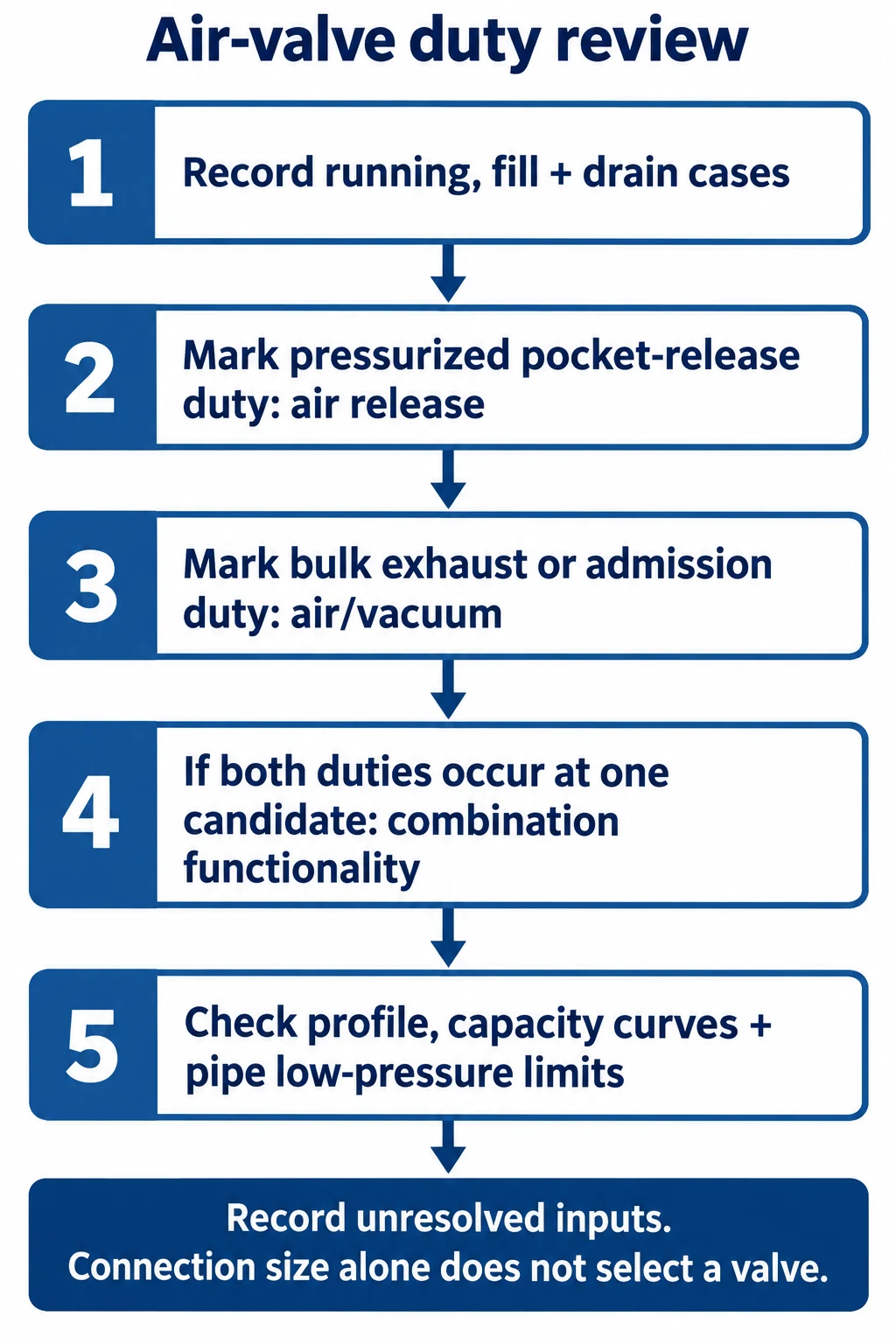
- Record running, fill and drain cases
- Mark pressurized pocket-release duty: air release
- Mark bulk exhaust or admission duty: air/vacuum
- If both duties occur at one candidate: combination functionality
- Check profile, capacity curves and pipe low-pressure limits
- Record unresolved inputs; connection size alone does not select a valve
Conclusion
The first useful selection is functional: pressurized release, bulk exchange, or both. Apply it to the operating profile, keep fill and drain demands separate, and align the air-flow basis before reading a capacity curve. That produces a reviewable requirement and exposes the missing inputs without pretending that a connection size is a final design.
Frequently asked questions
Does a small, low-velocity main automatically need no air valves?
No. Pipe size alone does not establish how air moves through the profile or what happens during filling, isolation and draining.
Does a combination valve solve every air-management duty?
It includes both functions, but their capacities, closing behaviour, location and connection still need the applicable system checks.
Can I use the working pressure as the pipe’s vacuum limit?
No. Obtain the applicable low-pressure or external-pressure limit separately and use it in the admission-duty review.