Material comparison sourced to named test methods, the constraints that actually govern sizing, and why condensation — not pressure — is what fails a branch run in the Gulf. Our scope is stated plainly: we supply to Ø110, not DN150–400 mains.
A chilled water pipe is the closed-loop pipework carrying water from the chiller to cooling coils and back. Typical design temperatures are 42–45 °F (5.6–7.2 °C) supply and 52–60 °F (11.1–15.6 °C) return (UFC 3-430-09, Table 2-1). The loop is sealed, so water recirculates rather than gets replaced. That makes joint integrity and condensation control matter more than raw pressure rating.
The design delta-T is not a free choice. ASHRAE 90.1 §6.5.4.7 requires a minimum 15 °F (8.3 °C) coil delta-T and leaving water no colder than 57 °F (13.9 °C) at design conditions (ASHRAE 90.1 §6.5.4.7, quoted in Trane Engineers Newsletter 48-2). European and UK practice uses a different basis. BSRIA BG 30/2007 Sheet W1 gives 6–12 °C for the primary loop and 10–15 °C for the secondary loop (BSRIA, per CIBSE Guide C / Guide B1). If your consultant works to CIBSE rather than ASHRAE, the spec’s temperature basis will differ from the figures above. Check which one governs before comparing offers.
Layer by layer, a chilled water system runs: chiller plant → primary and secondary distribution, commonly DN150–400 → risers → branch take-offs and FCU connections → coil. The bolded layer is where we operate.
IFANNova manufactures pressure pipe in Φ20–Φ110: UPVC 806 PN16 from 20×2.0 to 110×7.2 mm, and HDPE PN16 from 20×2.3 to 110×10 mm, both in 4 m lengths. PPR PN20 comes only in 20×2.8, 25×3.5 and 32×4.4 mm (per our catalogue). The section below sets out exactly what that range does and does not cover.
The branch layer is where material choice actually gets decided. This is our judgement from supplying that layer rather than a measured finding, and we publish no data behind it: fitting count per metre of run is higher on branch take-offs and FCU tails than on distribution mains, because every terminal served needs its own tee, reducer, isolating valve and final connection over a short length of pipe. The practical consequence is that an incomplete fitting range surfaces as adaptors improvised in a ceiling void rather than as a line on a purchase order.
Commercial chilled water mains commonly run DN150 to DN400. We do not make that range. Our pressure-pipe production stops at Φ110 (per our catalogue); our PPR line stops at 32 mm (per our catalogue). The table below is the actual manufactured range, unrounded.
| Product line | Series | Exact manufactured sizes (per our catalogue) | Pressure class / duty | Fitting depth |
|---|---|---|---|---|
| UPVC pipe 806 | WP55 pipe + 1806 fittings | Φ20–Φ110 (20×2.0 to 110×7.2, ×4 m) | PN16, pressure | 203 fitting items including ball valves and solvent cement (per our catalogue) |
| HDPE pipe | 603 / 604 compression fittings | Φ20–Φ110 (20×2.3 to 110×10) | PN16, pressure; marked “GERMANY STANDARD DIN8077/8078” (per our catalogue) | Two compression (no-fusion quick-connect) fitting series |
| PPR pipe 1103 | 1103 pipe + 1138 fittings | 20×2.8, 25×3.5, 32×4.4 mm only (×4 m). Above 32 mm: Coming soon | PN20, pressure | 75 fitting items (per our catalogue) |
| Brass fittings 2405 | 2405 + brass valves | 1/4 in – 1 in | Transitions to threaded/metal equipment | Fittings plus brass valves (per our catalogue) |
| PVC 902 | 902 drainage | Pipe Φ32–110; 1902 fittings Φ32–160 | Drainage / non-pressure. Excluded from chilled water pressure duty. | Do not order 902 for condensate-adjacent pressure work |
What the Φ110 ceiling covers in a real building: FCU and AHU take-offs, in-slab and ceiling-void branch runs, riser branch drops off a main we did not supply, villa and small-plant systems, and pool or process cooling loops within the diameter band. It does not cover plant-room headers or distribution mains.
Our strength is fitting depth at branch level. 203 UPVC fittings and 75 PPR fittings (per our catalogue) decide whether a take-off is clean or needs three adaptors in a ceiling void.
Insulation can be supplied alongside the pipe. Material, thickness and vapour barrier specification: Coming soon — advised per project, since condensation thickness depends on the design dew point at your site and has to be calculated case by case.
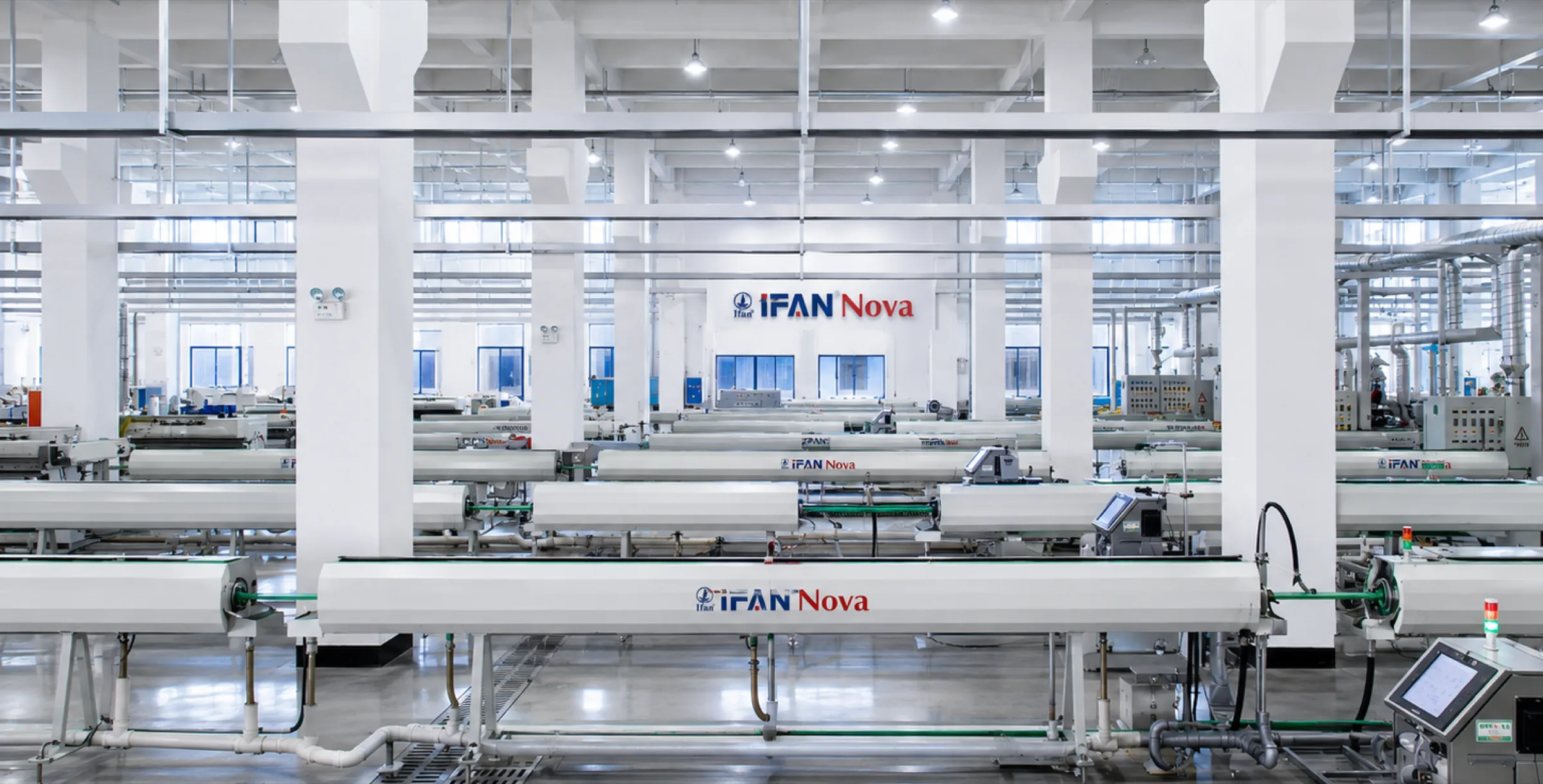
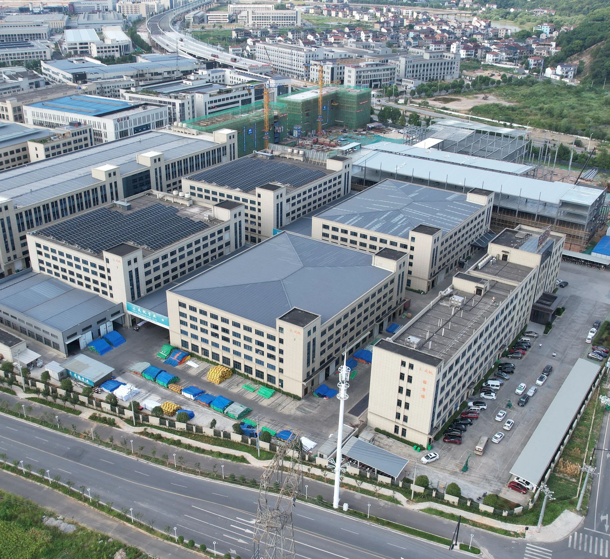
IFANNova is a French brand built to European design standards. Manufacturing is in our own facility, Zhuji Fengfan Piping Co., Ltd, Zhejiang: 30+ years, 1000+ employees, 118+ export countries, 10,000 moulds, 120,000 m² (per our catalogue). MOQ, lead time and pricing: Coming soon.
There is no single “chilled water pipe material” — there is a shortlist, and the deciding property is not the one datasheets lead with. Thermal conductivity gets quoted because it looks decisive. In practice the insulation settles it, not the pipe wall. What separates these materials in a 5.6–7.2 °C (UFC 3-430-09) service is notched impact strength at low temperature and how much the run moves. The table below draws on each manufacturer’s own published data, with the test method named per row. Conductivity values are not comparable across test standards and should never be presented as one authoritative table.
| Material | Governing standard | Thermal conductivity (test method) | Notched impact, 23 °C → 0 °C | Linear expansion | Jointing | Typical CHW role | From IFANNova |
|---|---|---|---|---|---|---|---|
| UPVC (PVC-U) | EN ISO 1452 — cold water up to and including 25 °C; EN ISO 15493 (industrial) | 0.16 W/m·K at 23 °C (DIN 52612-1 / ASTM C177, Marley); 0.10 W/m·K (ASHRAE Principles of HVAC 9th Ed. Table 1) | >8 → >3 kJ/m² (EN ISO 179-1/1eA, Georg Fischer); system range 0–60 °C | 0.07–0.08 mm/mK (Georg Fischer) | Solvent cement | Terminal branches, FCU connections, small systems | Y — Φ20–Φ110, 806 PN16 (per our catalogue) |
| PP-R | EN ISO 15874 — class-based, no lower temperature limit stated | 0.23 W/m·K at 23 °C (DIN 52612-1, Kalde); 0.24 W/m·K (Wavin) | 20 → 3.4 kJ/m², ≈83% loss (EN ISO 179-1/1eA, Georg Fischer PROGEF) | 0.16–0.18 mm/mK (Georg Fischer) | Socket/butt/electro fusion | Small branch and riser work where movement is compensated | Y — 20×2.8, 25×3.5, 32×4.4 mm only, PN20 (per our catalogue). Above 32 mm: Coming soon |
| HDPE (PE100) | EN 12201 — 20 °C reference temperature, PFA up to 25 bar | 0.4 W/m·K at 20 °C (DIN 52612, AGRU); 2.7 BTU·in/ft²/hr/°F (ASTM D177, Georg Fischer) | Toughness retained −50 to +60 °C; brittleness temperature < −118 °C (ASTM D746, Georg Fischer) | Higher than PVC-U; requires deliberate compensation | Fusion, or compression fittings | Buried and low-temperature runs, branch distribution | Y — Φ20–Φ110, PN16, compression series 603/604 (per our catalogue) |
| ABS | EN ISO 15493 (ABS / PVC-U / PVC-C industrial) | 0.17 W/m·K (EN 12664, Georg Fischer) | 42 kJ/m² at 23 °C, ≥10 kJ/m² at −40 °C (EN ISO 179-1/1eA, GF COOL-FIT) | 0.10 mm/mK (Georg Fischer COOL-FIT, no test method stated) | Solvent cement | Purpose-built secondary refrigeration and chilled water; max allowable operating temperature +40 °C | N — we do not manufacture ABS |
| Carbon steel (copper as metal reference) | Project/mechanical specification | Mild steel 64 W/m·K; copper 400 W/m·K (ASHRAE Principles of HVAC 9th Ed. Table 1) | Not the governing failure mode; corrosion and water chemistry are | Roughly an order of magnitude below plastics | Welded, grooved, brazed | Mains and headers at DN150–400 — outside our diameter range | N |
Two conclusions a design review can use. First, conductivity. NAIMA/Insulation Institute CI226 states verbatim that “the thermal conductivity of metallic piping is from 30x to 3,000x higher than typical plastic piping materials.” The order-of-magnitude gap is real. But CI226’s own Figure 1 shows the heat-loss difference between plastic and copper shrinking to very little once more than ½ in of insulation is applied. Conductivity explains why plastics behave differently bare. It is not a reason to skip insulation on chilled water.
Second, the property that does discriminate: cold-temperature toughness. PVC-U falls from >8 to >3 kJ/m² between 23 °C and 0 °C. PP-R falls from 20 to 3.4 kJ/m², about 83%. ABS still holds ≥10 kJ/m² at −40 °C, and PE100 stays tough down to −50 °C. Georg Fischer’s technical handbook puts it plainly: “Unlike PE, PP is not as impact-resistant below 0 °C… GF recommends ABS or PE for low temperature applications.” We sell PP-R, and that statement applies to our PP-R line as written. Chilled water at 5.6–7.2 °C sits above 0 °C. Site handling, cutting cold pipe and impact during installation do not.
ABS is the purpose-built secondary-refrigeration plastic, and we do not make it. If a specification calls for pre-insulated ABS, another supplier serves it better. On design life: ISO 9080 and ISO 12162 define 50 years at 20 °C as a design basis — a stress extrapolation, not a guaranteed field life. The TEPPFA meta-study is blunt about the weakest evidence base here: for pressure pipes, “no studies were found on polypropylene pipes.”
There is no universal winner. Five things set the material, in this order: diameter, the lowest fluid temperature the loop will ever see, whether the run is exposed outdoors, what jointing labour the site actually has, and whether the line is insulated. Answer those and the shortlist writes itself. Below is the path we would walk with a specifying engineer — including the points where the answer is “not us”.
| Line | Fits when | Does not fit when |
|---|---|---|
| UPVC 806, Φ20–Φ110, PN16 | Widest fitting count of our range — 203 items including ball valves and cement (per our catalogue); solvent-cement joints need no fusion plant; lowest thermal expansion of the plastics at 0.07–0.08 mm/mK (Georg Fischer). On the cold end, note what the standard does not do: EN ISO 1452 sets an upper limit of 25 °C for cold-water pressure duty and specifies no lower limit at all, so low-temperature suitability has to be established from the manufacturer’s own specification and impact data, not inferred from the standard’s upper bound | Fluid below 0 °C; heavy site impact exposure in cold handling |
| HDPE, Φ20–Φ110, PN16 | Best low-temperature toughness of anything we make; 603/604 compression fittings give no-flame, no-fusion assembly (per our catalogue; Georg Fischer). For outdoor runs, confirm the compound’s UV package against PPI TR-18 — carbon black content for our HDPE is not published; ask us before specifying exposed outdoor service | Where a large fitting/valve catalogue is required — our fitting depth is in UPVC |
| PPR PN20, 20 / 25 / 32 mm only | A final-connection and small-system product: FCU tails, terminal branches. Correctly made hot-melt and electrofusion joints are homogeneous; we publish no joint-strength test data — available on request | Sub-zero fluid, and cold-weather handling — notched impact falls from 20 to 3.4 kJ/m² between 23 °C and 0 °C, about 83 % (Georg Fischer). Chilled water at 5.6–7.2 °C stays above that test point, so this constrains site handling and storage temperature rather than the fluid duty. Expansion is 0.16–0.18 mm/mK, 2.2× PVC-U (Georg Fischer). Above 32 mm: Coming soon |
PVC pressure ratings are referenced to 20 °C and are not uprated below it. PIPA states “the strength of PVC increases as the service temperature is reduced… However, at the same time, the material becomes less tough and is more susceptible to impact damage” (PIPA TN012). For clean water the minimum service temperature “can be allowed to approach 0 °C” (PIPA TN012). The cold-service risk with PVC is handling impact, not pressure capacity. Protect pipe on site; do not chase a higher PN.
Cold contraction is a shipping and commissioning issue in the Gulf. PVC linear expansion is 7 × 10⁻⁵ /°C, so a 6 m length contracts 8.4 mm over a 20 °C drop (PIPA TN012). Pipe laid at midday ambient and commissioned on chilled water will move. Anchor, guide and allow for it at the design stage.
Sizing a chilled water pipe is not a lookup. It is a four-step check against limits that are mandatory in most jurisdictions. The method below is the one written into the US federal design criteria (UFC 3-430-09). It applies to a DN300 riser and to the Φ63 branch feeding a fan coil alike.
TABLE 1 — ASHRAE 90.1 Table 6.5.4.5, mandatory maximum velocity for piping over 12 in (I-P) / over 315 mm (SI); at and below those sizes the standard sets maximum flow rate in GPM by nominal pipe size instead. Values as published in the 2007 addenda to ASHRAE 90.1; cite the edition year your jurisdiction adopts.
| Annual operating hours | Other systems, pipe over 12 in (I-P) | Variable flow / variable speed, pipe over 12 in (I-P) | Other systems (SI, >315 mm) | Variable flow / variable speed (SI, >315 mm) |
|---|---|---|---|---|
| ≤ 2000 h/yr | 8.5 fps | 13.0 fps | 2.6 m/s | 4.0 m/s |
| > 2000 and ≤ 4400 h/yr | 6.5 fps | 9.5 fps | 2.0 m/s | 2.9 m/s |
| > 4400 and ≤ 8760 h/yr | 5.0 fps | 7.5 fps | 1.5 m/s | 2.3 m/s |
Read this table with care — it catches people out. Both columns of Table 6.5.4.5 are headed for large pipe — over 12 in (I-P) and over 315 mm (SI). Neither velocity band applies to a Φ63 or Φ110 branch, and our own range tops out at Φ110, far below that threshold. Within our range the standard constrains maximum flow rate in GPM by nominal size (2½ in and up), and below 2½ in it sets no limit at all; for branch work use the European practice bands in Table 2.
TABLE 2 — European design practice: velocity and pressure drop
| Parameter | Design value | Source |
|---|---|---|
| Velocity, steel ≤ 50 mm | 0.75–1.5 m/s (2.5–4.9 ft/s) | BSRIA BG 30/2007 Sheet W1, per CIBSE Guide C §4 |
| Velocity, steel > 50 mm | 1.25–3 m/s (4.1–9.8 ft/s) | BSRIA BG 30/2007 Sheet W1 |
| Velocity, corrosive water systems | 2 m/s maximum | BSRIA BG 30/2007 Sheet W1 |
| Pressure drop, > 50 mm recirculating | 100–300 Pa/m typical | BSRIA BG 30/2007 Sheet W1 |
| Pressure drop, starting point for calculation | 250 Pa/m | CIBSE Guide C, via BSRIA BG 30/2007 |
| Pressure drop, typical design | ~300 Pa/m (0.03 m head per metre) | CIBSE Journal CPD Module 32 |
| Velocity range, small systems to ≥ 50 mm | <1 m/s up to 3 m/s (9.8 ft/s) | CIBSE Journal CPD Module 32 |
| Minimum velocity (average / absolute) — heating water, not chilled water | 5 fps (1.53 m/s) / 2 fps (0.61 m/s) | UFC 3-430-09 §4-2.1.4.1, “HTW and MTW Piping Sizing” (high- and medium-temperature heating water; UFC states no minimum velocity for chilled water in §4-2.1.5) |
Why there is no diameter-versus-GPM chart on this page. A credible flow chart is derived from the licensed ASHRAE Fundamentals friction curves, which we cannot reproduce or re-derive. An invented table would fail exactly where it matters — at the velocity limit. If a vendor hands you a sizing chart, check its implied velocities against ASHRAE 90.1 Table 6.5.4.5 above before you use it. That check takes a minute and catches most bad charts.
What binds within our range. Across Φ20–Φ110 branch runs and FCU connections, the deciding constraint is almost always velocity and the noise that comes with it, not the pressure class. UPVC 806 is PN16, HDPE is PN16, and PPR is PN20 (per our catalogue). All sit far above the working pressure of a terminal branch on a building chilled water circuit. Size to the velocity and pressure-drop limits first. The pressure rating will not be the limiting factor.
The criterion comes first, because everything follows from it: condensation forms when the outer surface of the insulation system falls below the dew point of the surrounding air. “The design goal is to keep the surface temperature above the dew-point temperature of the surrounding air” (NIA Insulation Design Guide). The control variable is that outer surface temperature, not the pipe material’s thermal conductivity.
Plastic pipe is routinely mis-sold on this point. A PP-R manufacturer states it against its own commercial interest: “even Aquatherm piping cannot be guaranteed to not sweat when exposed to the proper conditions”, and “all piping installations where cold or chilled water is to be carried in the piping or where the surface temperature of the piping is expected to be below the ambient temperature shall be insulated per code” (Aquatherm Tech Bulletin, Piping Condensation). The magnitudes explain why. A CPVC pipe wall at 1/8 in is R-0.13, against R-4.3 for 1 in glass wool — roughly 33x (TIAC Times). Measured heat-loss curves agree, and it is worth naming what was measured. NAIMA CI226 Figure 1 is a 2 in tube carrying water at 140 °F (60 °C) in still air at 75 °F (23.9 °C); on that test the difference between plastic and copper “becomes very small” above 1/2 in of insulation (NAIMA CI226 Figure 1). Owens Corning, also on 140 °F (60 °C) hot water in 1 in bare plastic pipe, measured 34.26 BTU/hr falling to 7.95 BTU/hr with 1 in glass wool — a 77% reduction (via TIAC Times). Both are hot-side tests, so read them for direction rather than for magnitude: they establish that once insulation is applied it, not the pipe wall material, sets the heat transfer, and that ranking does not reverse when the temperature difference is inverted for chilled service. What they cannot do is give you a chilled water thickness. Low conductivity is a heat-gain argument, never a condensation exemption.
Table 6.8.3-2, fluid 40–60 °F (4.4–15.6 °C), conductivity basis 0.21–0.27 Btu·in/h·ft²·°F at 75 °F mean (ASHRAE 90.1-2019 Addendum aq). Always cite the edition year — values move between editions.
| Nominal pipe size | Min. thickness (in) | SI size | SI thickness (mm) |
|---|---|---|---|
| < 1″ | 0.5 | < 25 mm | 13 |
| 1 to < 1-1/2″ | 0.5 | 25 to < 40 mm | 13 |
| 1-1/2 to < 4″ | 1.0 | 40 to < 100 mm | 25 |
| 4 to < 8″ | 1.0 | 100 to < 200 mm | 25 |
| ≥ 8″ | 1.0 | ≥ 200 mm | 25 |
Footnote b, verbatim: “These thicknesses are based on energy efficiency considerations only. Issues such as water vapor permeability or surface condensation sometimes require vapor retarders or additional insulation.” Footnote c, verbatim: “For direct-buried cooling system piping, insulation is not required.” For a material outside the tabulated conductivity band, footnote a gives T = r{(1 + t/r)^(K/k) − 1}, where T = minimum thickness for the alternative material, r = actual outer radius of the pipe, t = the tabulated thickness for that fluid temperature and pipe size, K = the alternative material’s conductivity at the stated mean rating temperature, and k = the upper limit of the tabulated conductivity range (ASHRAE 90.1).
NIA Table 1 — insulated tank holding liquid at 40 °F in 80 °F ambient (surface coefficient 1.2 Btu/h·ft²·°F, insulation conductivity 0.30 Btu·in/h·ft²·°F). Read it for the shape of the RH relationship, not as a pipe thickness table; for pipe, use NIA’s horizontal-pipe condensation calculator.
| Ambient RH | 30% | 40% | 50% | 60% | 70% | 80% | 90% | 95% |
|---|---|---|---|---|---|---|---|---|
| Thickness to prevent condensation (in) | 0.1 | 0.2 | 0.3 | 0.5 | 0.7 | 1.3 | 2.9 | 6.0 |
From 50% to 90% RH the requirement multiplies roughly tenfold (0.3 → 2.9 in). NIA and IIAR draw the same practical line: “above a relative humidity of around 90-95% it takes an unrealistic and impractical insulation thickness to prevent condensation”, and “the insulation thickness required to prevent surface condensation asymptotically approaches infinity as the r.h. approaches 100%” (IIAR).
| Rank | Factor | Published statement |
|---|---|---|
| 1 | Relative humidity | “The influence of r.h. on surface condensation is very large, especially as the r.h. gets above around 70-80%.” (NIA Insulation Outlook, Part 1) |
| 2 | Insulation conductivity | “The insulation material used, and its thermal conductivity, has a direct, strong impact on the thickness required to prevent surface condensation.” (NIA) |
| 3 | Surface emittance | “Materials with lower emittance, like most metals, yield a colder outer surface, making surface condensation more likely” — bright metal jackets work against you (NIA) |
| 4 | Ambient temperature | “A higher ambient temperature can lead to a slightly increased insulation thickness … but this influence is small.” (NIA) |
ASTM C1136 (2023) classifies flexible low-permeance vapour retarders into Types I–VI. We have verified two of them, and only through the US federal specification that invokes them: Type I at a maximum 0.02 perms with 50 Beach units minimum puncture resistance, and Type II at 0.02 perms with 25 Beach units (UFGS 23 07 00 §2.2.9.3 — cited via the federal spec, not from the C1136 text, which is paywalled). Per-type values for Types III–VI: Coming soon. ASTM C1136 covers flexible vapour retarders of 0.15 perm or lower for surfaces between −20 and 150 °F (−29 to 66 °C). Chilled water practice is stricter than that ceiling: 0.02 perms is the recommendation for CHW systems (Johns Manville), and an ASJ Max jacket achieves 0.02 perm by ASTM E96 Procedure A (Owens Corning). Get this wrong and moisture, not heat, kills the system. 98% of insulation system problems are moisture-related, and each 1% moisture gain raises thermal conductivity by 23% in open-cell materials (Owens Corning FOAMGLAS). A separately sourced figure puts the loss at 7.5% of thermal performance per 1% moisture, with water itself at 4.1 Btu/(hr·°F·ft²/in) at 75 °F mean (NIA Insulation Outlook, Condensation Control). The two figures come from different sources and different test bases — we quote both rather than averaging them.
| Material | Conductivity | Vapour performance | Standard |
|---|---|---|---|
| Mineral fibre / glass wool | 0.032 W/m·K at 10 °C (Owens Corning) | Jacket-dependent; ASJ Max 0.02 perm, ASTM E96 Proc. A | ASTM C547 Types I and IV |
| Elastomeric NBR/EPDM | 0.28 BTU·in/hr·ft²·°F (ASTM C534, via NAIMA CI226) | 0.05 perm-inch | ASTM C534 Type II |
| Cellular glass | 0.043 W/m·K at 10 °C (Owens Corning FOAMGLAS) | µ = infinity; capillarity none; <0.2% moisture by volume (ASTM C240) | ASTM C552 |
On the calculation itself: in European practice the recognised calculation rules for surface temperature and for preventing surface condensation on building-services insulation sit in ISO 12241. We are not reproducing its clauses or formulae here, because we were unable to obtain the current text beyond a cover preview and we do not quote standards we have not read. If your specification is written to European rules, get the current edition through your consultant or a standards reseller and calculate against it. Treat every table-derived thickness on this page — including the ones above — as a starting point to be checked against your project’s design dew point, not as an answer.
Our position: IFANNova can supply insulation alongside the pipe. Specification — material, thickness and vapour barrier — is advised per project rather than quoted from a chart. Insulation material, thickness and vapour barrier data: Coming soon. All insulation figures above are published third-party data, attributed to their sources, and do not describe IFANNova-supplied products.
This section gives you a method, not a table. That is deliberate, and the reason is worth stating before anything else.
We could not obtain first-hand, publicly citable design data for Gulf sites, so we are not publishing any. We went looking for it: ASHRAE climatic design conditions for the individual Gulf stations, the insulation clauses of Dubai Municipality’s Green Building Regulations, DEWA’s requirements, Estidama, and the Saudi Building Code / SASO. Every route ended in a paywall, a broken document link, or an interactive database we could not cite from. Rather than fill the gap with numbers scraped from aggregator sites or reverse-engineered from a manufacturer’s US selection table, we are leaving it empty and telling you where to go instead. Any supplier who hands you a ready-made “Gulf insulation thickness table” should be asked, first, which station’s design dew point it was built on and from which published source — because we looked, and we could not find one.
What still holds without a single number is the engineering logic, and it is the part that actually changes a specification.
Condensation is governed by the design dew point of the air around the insulation, not by the dry-bulb temperature quoted in a tender (NIA). Dew point is a humidity quantity. Coastal sites and inland sites in the same country do not share a humidity regime: a site on the water and a site several hundred kilometres inland see different moisture loading, so they do not produce the same design dew point, and therefore they do not produce the same required insulation thickness or the same vapour-barrier demand. The relationship is steep, not gentle — the published NIA table earlier on this page shows required thickness rising roughly tenfold between 50% and 90% ambient RH at a fixed fluid and ambient temperature (NIA Table 1, computed for an insulated tank at its stated test conditions — read for the shape of the relationship, not as a pipe thickness).
Two consequences follow directly, and neither needs a specific number to be true:
The design dew point is a project input, the same class of input as the design flow rate. It belongs in the specification, and someone on the project is already responsible for producing it. The practical route:
What we will not do: we will not compute a thickness for your site and publish it as a recommendation, and we will not reproduce a table we cannot source. Where we have insulation figures on this page they are third-party published data, attributed, with the test conditions named. Verified local-code references for Gulf jurisdictions: Coming soon — when we can cite the clause text itself.
At terminal branch level, the pipe is rarely what stops a job. A missing reducing tee stops it. So does a valve in the wrong pressure class, or a fusion joint that fails hydrostatic test on a Thursday afternoon. Below: what each jointing method demands from the site, and what we can put in a container against it.
| Material / series | Jointing method | What the site must have | Fitting inventory |
|---|---|---|---|
| UPVC 806 PN16 (WP55 pipe, 1806 fittings), Φ20–Φ110 | Solvent cement | Clean square cuts, correct cement, cure time before test. Solvent bonding does not produce a homogeneous joint and reduces chemical resistance (GF Technical Handbook p.6) | 203 items including ball valves and glue (per our catalogue) |
| PPR PN20 (1103 pipe, 1138 fittings), 20/25/32 mm only | Socket fusion (hot-melt) and electrofusion | Calibrated fusion tooling, power, trained operator, temperature-controlled dwell. Correctly made joints are homogeneous; we publish no joint-strength test data — available on request | 75 items (per our catalogue) |
| HDPE PN16, Φ20–Φ110 | Compression, series 603 and 604 (no-weld quick-connect) | No fusion, no flame, no threading — spanner work only | 603 / 604 compression series (per our catalogue) |
| Brass 2405, 1/4in–1in, plus brass valves | Threaded transition | Used at metal transitions and terminal connections. Threading costs integrity and pressure capacity (GF Technical Handbook p.6) | 2405 fittings 1/4in–1in and brass valves (per our catalogue) |
Fusion is the strongest option: it creates a homogeneous transition between components (GF Technical Handbook p.6). It is also where failures are human rather than material. Fusion branch holes must be 1/24–1/8 in (1–3 mm) smaller than the branch OD; “An oversized hole will result in an incomplete fusion and cause leaks” (Aquatherm Installer Manual §2.25). Other documented workmanship failures: stress whitening or cracks at a cut require marking and removing the damaged section, cutting a few inches past the damage (Aquatherm §2.5); the wrong blade or a slow cut overheats the pipe (Aquatherm §2.4); fusing mixed SDRs rates the whole system to the thinnest wall (Aquatherm §2.51).
Hence compression on Gulf sites. No hot-work permit. No fusion machine calibration to argue about with the QA/QC engineer. Retrofit work stays possible in occupied buildings. The hot-work and fusion-calibration failure modes are removed; ordinary assembly discipline still applies.
The other side of that ledger, because it is rarely printed by whoever sells the fittings: a compression joint has its own workmanship requirements. The cut has to be square and deburred, the pipe end round and unscored, the sealing surfaces and the o-ring undamaged by site handling, the insert seated, and the nut tightened to the fitting manufacturer’s torque — under-tightened it weeps, over-tightened it distorts the ferrule. Compression removes hot work and machine calibration from the site; it does not remove workmanship from the joint. We are not aware of independent published failure statistics ranking jointing methods in chilled water service, and we do not claim one method has fewer field failures than another.
Item counts above are catalogue-verified. Availability of an individual part number, packing and lead time: Coming soon.
Plastic buys corrosion immunity and a fraction of the handling weight. It charges you back in support spacing and thermal movement. Here is that side of the ledger, with every number attributed to whoever published it.
Thermal movement. PP moves at 0.16–0.18 mm/mK against PVC-U at 0.07–0.08 mm/mK — roughly 2.2 times (Georg Fischer). ABS sits at 0.10 mm/m·K (GF COOL-FIT manual, coefficients of linear expansion table — no test method stated). Within our range, UPVC 806 is the lower-movement choice for long terminal branch runs. PPR needs the compensation detail drawn before it goes up. A manufacturer rule of thumb: non-fibre-composite pipe in temperature-varying service needs expansion control every 30 ft (9.1 m), and every 120 ft (36.6 m) on long runs. Risers can be linearly isolated floor by floor (Aquatherm Installer Manual §3.15).
Clamping doctrine. Plastics “can and should be allowed to move after commissioning” (GF COOL-FIT manual p.15). Never create a fixed point by clamping the outer wall — “This can cause deformation and physical damage to the pipe, damage that sometimes only later becomes visible” (GF COOL-FIT manual p.31). Metal clamps need at least 0.125 in (3 mm) of elastomeric lining (Aquatherm §3.3). The Gulf-specific detail most likely to generate a site callback: metal in direct contact with chilled pipe “may sweat in certain chilled applications, even if the pipe itself shows no signs of condensation” (Aquatherm §3.3). In high-humidity areas, specify a non-crushable pipe shield.
| Parameter | Value | Source |
|---|---|---|
| ABS PN10/SDR17 bracket spacing, ≤20 °C | d63 1300 mm; d110 1800 mm; d160 2200 mm | GF COOL-FIT manual p.33 |
| Same, at 30 °C | d63 1200 mm; d110 1650 mm | GF COOL-FIT manual p.33 |
| Correction factors | Risers ×1.3; SDR11/PN16 ×1.08 | GF COOL-FIT manual p.33 |
| Filled vs empty weight, SDR 11 MF RP 12 in | 17.24 lb/ft empty → 52.23 lb/ft filled (water ≈67% of filled weight) | Aquatherm Design Guide §1.06 |
| Pre-insulated systems | “Preinsulated pipe requires about 30 % less hangers than standard plastic pipe” | GF COOL-FIT manual p.8 |
| UPVC handling weight | 1/6 of brass, 1/5 of steel | per our catalogue |
| IFANNova support-spacing table | Coming soon — we publish none of our own | — |
Two readings of that table matter. First, size the hanger and the structural check on filled weight, not empty — water is about two thirds of the load at 12 in (Aquatherm §1.06). The catalogue’s 1/6-of-brass figure is an installation-labour argument, not a structural one. Second, if you are comparing our pipe-plus-insulation supply against a pre-insulated system, put the ~30% hanger count difference in the comparison (GF COOL-FIT p.8).
UV and outdoor storage — the one operationally critical Gulf fact. PPI TR-18 (2019) limits non-black PP pipe to a cumulative 3 months of outdoor storage unless shaded. PE for long-term outdoor use needs ≥2% well-dispersed carbon black per ASTM D3350, which can give 50+ years. Standard-grade PVC per ASTM D1784 with TiO₂ stores outdoors at least 1 year. TR-18 also states that “a specific period of exposure in Arizona is more detrimental than in New Hampshire due to the obvious extra hours of UV exposure and, less obviously, to the higher ambient temperatures encountered”. Treat a Gulf laydown yard as severe. Weathering plus external stress together shortens life markedly — stressed PE specimens degraded earlier. Once installed, UV damage to PVC is superficial: yellowing is limited to the outermost 0.001–0.002 in, and after two years of exposure tensile strength and modulus were unaffected, with impact reduced but still above new-pipe requirements (Uni-Bell UNI-TR-5).
Plastic branch pipe removes one failure mode from a chilled water system. The sources say it in their own words. Aquatherm states that “Polypropylene will not corrode and is not affected by scaling, the way many other materials are. It also does not support microbiological growth” (Aquatherm FAQ). The Plastics Pipe Institute lists resistance to corrosion, tuberculation and deposits, plus chlorine and chloramine resistance, among the properties of PP-R and PP-RCT in building construction (PPI). GF describes its COOL-FIT material as “biologically inert; no support of microbial growth” and cites “low pressure losses due to smooth surfaces” and “Zero corrosion… Smooth pipes: no encrustation, low pressure drops” (GF COOL-FIT manual, pp. 8 and 18). A terminal branch has to hold its design flow for decades without the bore closing in. A wall that does not tuberculate is a checkable engineering benefit.
The counterweight matters more. In a closed loop the controlling variable is water chemistry, not pipe material. Reporting ASHRAE’s corrosion guidance, CIBSE Journal (September 2015) puts it plainly: “A properly inhibited closed-loop hot or cold system should last the lifetime of a building if its water and/or steam chemistry is maintained properly.” Potable make-up water carries 6–12 mg/L dissolved oxygen (CIBSE Journal / ASHRAE). That is why closed systems benefit from oxygen scavengers such as ascorbic acid or sodium sulphite (CIBSE Journal / ASHRAE). The same guidance notes that correct water chemistry control can eliminate the need for troublesome dielectric fittings. That applies directly where our brass 2405 fittings meet plastic in a mixed system. If the chemistry regime is wrong, changing the branch material will not save the loop.
We searched for comparative corrosion-rate data (in mpy or mm/yr) between plastic and steel in chilled water service and found none we could cite to a published source, so we quote no figure. If a supplier quotes one to you, ask for the test standard it was measured to and the water chemistry it was measured under — without both, the number cannot be compared to anything. For our own PP-R lines the catalogue does state three things qualitatively: the material is non-toxic and suitable for potable water, it resists acids and alkalis, and it carries not more than 10 % recycled material without the quality being affected (per our catalogue). What the catalogue does not give is any of that as a tested figure against a named standard: test-standard-referenced material data: Coming soon — available on request.
Procurement runs a compliance check before a technical one. This section lists the standards framework behind each line, the certification names on record, and the things we cannot yet evidence in writing. Holding back that last part only delays the audit.
| Line | Standard | What the standard actually says about temperature |
|---|---|---|
| UPVC (PVC-U) | EN ISO 1452 | Pressure water supply “up to and including 25 °C (cold water)”; water and waste up to and including 45 °C, derated per Figure A.1 between 25 °C and 45 °C (ISO 1452-2:2009). No lower temperature is specified. |
| PPR (PP-R) | EN ISO 15874 | Scope is set by class of application per Table 1, with upper design limits only: “Values of TD, Tmax and Tmal in excess of those in Table 1 do not apply” (ISO 15874-1:2013). Cold-water design stress basis σLPL 6.93 MPa at 20 °C / 50 years (ISO 15874-2:2013, Annex A). No minimum service temperature. |
| HDPE (PE) | EN 12201 | Allowable operating pressure PFA up to 25 bar at a 20 °C reference temperature; Annex A covers constant temperatures above 20 °C up to 50 °C (BS EN 12201-1:2024). No minimum service temperature. |
| Industrial reference set | EN ISO 15493 / EN ISO 15494 | ABS, PVC-U and PVC-C industrial piping systems (EN ISO 15493) and PP industrial systems (EN ISO 15494), per the BSI/NBS publication index — the framework most industrial specifications cross-reference. |
One correction, because most competitor pages get it wrong: none of these three standards specifies a minimum service temperature. A “0 °C floor mandated by the standard” comes from a manufacturer datasheet, not from EN ISO 1452, EN ISO 15874 or EN 12201. The reverse error is just as common and appears on supplier pages arguing for plastic: reading an upper limit as if it certified everything beneath it. It does not. An upper bound is silent about the lower end, so a standard’s 25 °C cold-water ceiling tells you nothing about suitability at 6 °C. What settles low-temperature suitability is the manufacturer’s stated service range for the specific product plus its impact data at low temperature — the figures in the material table above — not a clause in the standard.
What the standards do instead is test at cold. Impact resistance for PP-R, PP-B and PP-RCT is mandatory at a test temperature of 0 °C, TIR ≤ 10 %, 10 specimens, to ISO 9854-1/-2 (ISO 15874-2:2013, Table 10 — PP-H is tested at 23 °C). And 0 °C is the standard worst-case point for the round-the-clock impact method, TIR maximum 10 %, with −20 °C recommended in NOTE 1 if colder testing is required (ISO 3127:1994). Cold service is already inside the qualification regime. It needs no datasheet floor to justify it.
On HDPE, check what ships on the goods: the pipe body carries “GERMANY STANDARD DIN8077/8078” (per our catalogue). Match the marking to your submittal wording before it reaches the consultant — the marking is what site QA reads.
IFANNova is a French brand, designed to European standards and manufactured in our own facility by Zhuji Fengfan Piping Co., Ltd, Zhejiang, China (per our catalogue). We state it here because any serious vendor audit will surface it, and a buyer who finds it themselves reads it as concealment.
What is the largest chilled water pipe you supply? Φ110 mm in UPVC 806 (Φ20–Φ110, 110×7.2 mm ×4 m, per our catalogue) and in HDPE PN16 (Φ20–Φ110, 110×10 mm, per our catalogue). PPR PN20 stops at 32×4.4 mm (per our catalogue). We do not make DN150–400 mains, headers or plant-room pipework. Our scope is terminal branch runs, FCU connections and small systems. Anything above Φ110 we cannot quote — better you know that before the BOQ is written.
Do plastic chilled water pipes need insulation? Yes. The criterion is surface temperature versus ambient dew point: condensation forms whenever the outer surface sits below the dew point of the surrounding air (NIA). Low pipe-wall conductivity does not change this. PP-R manufacturer Aquatherm states in its own technical bulletin that “even Aquatherm piping cannot be guaranteed to not sweat when exposed to the proper conditions,” and that “all piping installations where cold or chilled water is to be carried in the piping or where the surface temperature of the piping is expected to be below the ambient temperature shall be insulated per code” (Aquatherm). Its only exceptions are direct-buried chilled water piping and most domestic cold water piping (Aquatherm). ASHRAE 90.1 Table 6.8.3-2 footnote c agrees, waiving insulation for direct-buried cooling system piping.
What are typical supply and return temperatures? UFC 3-430-09 Table 2-1 gives 42–45 °F supply and 52–60 °F return, which convert to 5.6–7.2 °C supply and 11.1–15.6 °C return. The Fahrenheit values are the ones the source publishes; UFC’s own SI figures are 6–7 °C supply and 11–16 °C return, and the finer conversions above are derived, so quote the °F figures when you cite UFC. European practice is stated on a different basis: a primary-circuit range of 6–12 °C (BSRIA BG 30/2007).
What velocity limit applies? ASHRAE 90.1 Table 6.5.4.5 bands maximum flow by annual operating hours (values below as published in the 2007 addenda — check the edition year adopted by your jurisdiction): ≤2000 h/yr, 8.5 fps (other) / 13.0 fps (variable flow, variable speed); >2000 to ≤4400 h/yr, 6.5 / 9.5 fps; >4400 to ≤8760 h/yr, 5.0 / 7.5 fps (ASHRAE 90.1). These velocity bands apply to piping over 12 in (over 315 mm). At and below that size the standard limits maximum flow rate in GPM by nominal pipe size, and sets nothing below 2½ in — so for Φ20–Φ110 branch work the binding checks are the European practice bands and noise, not this table. The hours caveat matters in the Gulf: near-continuous cooling puts most systems in the strictest band.
How thick should insulation be in Dubai or Doha? We do not publish a number, and we would not trust one that arrived without a station name attached to it. Thickness has to be calculated against your own site’s design dew point, which is a project input you get from the MEP consultant along with the design dry-bulb and the ambient RH used for the mechanical calculations. Ask for it by weather station, not by city. Note also that ASHRAE 90.1 Table 6.8.3-2 footnote b states its thicknesses “are based on energy efficiency considerations only” (ASHRAE 90.1) — that table is not a condensation answer anywhere in the world, including a temperate climate. The Gulf section above sets out the full input list and the order to work through it.
Can each material be used for chilled water?
| Line | Chilled water use | Size band we can deliver |
|---|---|---|
| UPVC 806 PN16 | Yes, with insulation. Low conductivity is not a condensation exemption. | Φ20–Φ110 (per our catalogue) |
| PPR PN20 | Yes, within its rated class. Note that high thermal expansion and reduced 0 °C impact strength apply to PP-R generally. | 20, 25, 32 mm only (per our catalogue) |
| HDPE PN16 | Yes; retains impact toughness at low temperature. | Φ20–Φ110 (per our catalogue) |
Do you supply insulation? Yes, alongside the pipe. Material, thickness and vapour barrier specification: Coming soon, advised per project.
MOQ, lead time, pricing, certificate numbers? Coming soon — contact us and we will confirm against your enquiry.
Where are the products made? IFANNova is a French brand working to European design standards, manufactured in our own facility by Zhuji Fengfan Piping Co., Ltd in Zhejiang, China (per our catalogue).
We would rather tell you in one email that a line is outside our range. Our pressure pipe ceiling is Φ110 for UPVC and HDPE, and 32 mm for PPR (per our catalogue). If your bill of quantities is built around DN150–400 mains, we are not the supplier for that portion. Send us the terminal branch and FCU connection scope instead.
To quote, send these six inputs:
Send it to our sales desk and it reaches an engineer, not a form queue. Our catalogue states 24h online service across 118+ export countries (per our catalogue). Lead time, price and MOQ: Coming soon.
A worked chilled water pipe sizing example: cooling load to flow, flow to diameter, with the velocity and pressure-drop limits that govern each step and where the…
What one floor of chilled water branch pipework actually consumes: valve authority, strainer sizing, and the fitting counts that stop a site when they are missed.
Primary, primary-secondary and variable-flow chilled water loops compared — and which layer of the system a branch pipe supplier actually serves.
