Our chilled water piping guide lists thermal expansion coefficients alongside the other material trade-offs and stops there. A coefficient is a material property, not a design. This article is the design: how to convert that coefficient into millimetres of movement, how to convert millimetres into a loop leg you can dimension on a drawing, where the anchors go, where the guides go, and which of those four steps actually fails on site.
It is written for chilled water, which changes the problem in a way most expansion literature ignores. Almost every published worked example assumes the pipe gets hotter than the day it was installed. Chilled water usually gets colder. The pipe contracts, the anchors are loaded in the opposite direction, and any compensator sized on a one-way assumption is sized wrong.
The linear expansion calculation is unambiguous. Georg Fischer states it in US units for polypropylene pressure systems as:
ΔL = L · ΔT · δ
The handbook writes the dimensional check out explicitly — (inch) = (inch) · (°F) · (inch/inch·°F). Run it on your own spreadsheet before you trust it. [Georg Fischer, Technical Handbook, Polypropylene Pressure Piping Systems (PROGEF), p.50, “Determining the Length Change (ΔL)”]
The term that gets dropped is ΔT, and specifically what it is measured from. Georg Fischer is direct: “If the operating temperature is higher than the installation temperature, then the pipe becomes longer. If, on the other hand, the operating temperature is lower than the installation temperature, then the pipe contracts its length. The installation temperature must therefore be incorporated into the calculation, as well as the maximum and minimum operating temperatures.” [GF PROGEF handbook, pp.50–51]
Georg Fischer’s coolant example is the one worth copying, because it is bidirectional rather than the usual hot-service single case. For a 315 in run of PP-H, the three temperatures are:
| Temperature | Symbol | °F | °C |
|---|---|---|---|
| Installation temperature | Tv | 73 | 22.8 |
| Coolant operating temperature | T1 | 40 | 4.4 |
| Defrost / cleaning temperature | T2 | 95 | 35 |
Applying ΔL = L · ΔT · δ in both directions from the installation temperature:
| Movement | Symbol | Calculation | ΔL (in) |
|---|---|---|---|
| Contraction | ΔL1 | 315 · 33 · 0.000083 | 0.86 |
| Expansion | ΔL2 | 315 · 22 · 0.000083 | 0.58 |
| Total movement range the flexible section must accommodate | — | — | 1.44 |
[GF PROGEF handbook, pp.50–51, Example 1, coolant pipe; δ = 0.000083 in/in·°F as used in the handbook’s design calculation, p.50]
Note what the arithmetic does. Neither figure alone sizes the compensator. The pipe swings from 0.86 in shorter than installed to 0.58 in longer, and the loop has to survive the full 1.44 in stroke. A designer who calculated only the 40 °F case would undersize the arm by roughly 40%. On a chilled water system that never sees a cleaning or defrost cycle the expansion leg genuinely disappears — but you must be certain that cycle does not exist, including during commissioning with the chillers off in an unconditioned plant room.
We found an internal inconsistency inside the Georg Fischer PP handbook itself, and it silently propagates into a design. The material-properties section states polypropylene shows thermal expansion of “0.16 to 0.18 mm/mK”. The design formula section uses δ = 0.000083 in/in·°F, which converts to 1.494 × 10⁻⁴ m/m·K, or 0.149 mm/(m·K) — below the stated 0.16–0.18 range. A designer working from the body text gets roughly 7–21% more calculated expansion than the handbook’s own sizing tables assume. [Georg Fischer PP handbook, properties section vs. p.50 formula section]
Do not cite both figures as though they agree. Pick the one belonging to the calculation route you are using — if you are sizing from the manufacturer’s tables, use the coefficient those tables were built on — and state which on the drawing.
Material-by-material coefficients are tabulated in the pillar guide and are not repeated here. What matters for compensation design is not the table but the size of the disagreement between sources, because that is what decides whether your ΔL is trustworthy.
The Plastic Pipe and Fittings Association tabulates coefficients determined per ASTM D696 alongside Young’s modulus and the theoretical stress in a fully restrained pipe. Its PP figure of 4.3 × 10⁻⁵ in/in·°F is roughly half the 8.3 × 10⁻⁵ Georg Fischer uses in its design formula. Over 100 ft (1,200 in) at ΔT = 25 °F, ΔL = 1,200 · 25 · 4.3 × 10⁻⁵ = 1.29 in against 1,200 · 25 · 8.3 × 10⁻⁵ = 2.49 in — an almost 2:1 disagreement between two respectable sources on the same generic material. This is not sloppiness. PP is a family of materials, and grade, fibre content and test basis all move the number. It is, however, a hard argument against designing from a generic material coefficient. Use the coefficient published for the specific pipe you are buying. If the supplier will not publish one, that is a procurement finding, not a rounding problem. [PPFA (Plastic Pipe and Fittings Association) User Bulletin, “Provisions for Expansion and Contraction”, 2014, “Factors for Common Piping Materials” table, p.3; coefficients determined per ASTM D696]
PPFA quantifies the movement gap plainly: unconstrained PE pipe “will expand or contract at least ten times the distance of steel pipe of the same length.” A 10 °F swing moves 100 ft of unconstrained pipe as follows:
| Material | Coefficient (in/in/°F) | Movement of the run |
|---|---|---|
| Polyethylene | about 9 to 12 × 10⁻⁵ | 1.0 to 1.2 inches |
| Steel | about 1 × 10⁻⁵ | about 0.10 inch |
[PPFA User Bulletin, pp.2–3]
But the force story inverts. PPFA: “for constrained polyethylene pipe, the stresses developed due to this movement are substantially lower than that of a steel line. This is due to the lower modulus of elasticity.” PPFA’s own figures confirm it, for a fully restrained line at ΔT = 70 °F:
| Material | E (psi) | α (in/in·°F) | Restrained stress (psi) |
|---|---|---|---|
| HDPE | 0.12 × 10⁶ | 9.0–12.0 × 10⁻⁵ | 756 to 1,008 |
| Steel | 30.0 × 10⁶ | 6.7 × 10⁻⁶ | 14,070 |
Each is reproducible as stress = E · α · ΔT. [PPFA User Bulletin, “Factors for Common Piping Materials” table p.3 and pp.2–3]
The design consequence is the single most useful sentence here: on a plastic chilled water line the governing risk is displacement and buckling, not anchor thrust. Steel practice teaches you to fear the force. Plastic practice should teach you to fear the movement — the pipe wandering out of a hanger, bearing on a duct, snapping a fitting in bending, or bowing laterally between guides. Designers arriving from steel routinely over-engineer the anchor steelwork and under-engineer the guiding.
Once you have ΔL, the compensating leg is sized by a square-root relationship that every source shares in form and disagrees on in constant.
Georg Fischer, for polypropylene:
a = k · √(ΔL · d) where k = 30 for PROGEF Standard/Natural polypropylene
a = length of flexible section, ΔL = change in length, d = outside diameter of pipe. [GF PROGEF handbook, p.51, “Formula for Flexible Sections (a)” and Table 8]
Units warning, verified by back-calculation. We checked this formula against the handbook’s own Table 8, for 250 mm pipe (OD = 9.843 in):
| ΔL (in) | a computed from a = k·√(ΔL·d) (in) | a published in the handbook table (in) |
|---|---|---|
| 0.1 | 29.8 | 30 |
| 1.0 | 94.1 | 94 |
| 2.0 | 133.1 | 133 |
| 10.0 | 297.6 | 298 |
The match confirms that ΔL and d are both in inches and a comes out in inches — despite the table header labelling the pipe in millimetres. A millimetre diameter produces a leg roughly five times too long, which usually gets caught. A millimetre ΔL with an inch diameter usually does not.
The same form with a different constant governs PE100: k = 26, with δ = 0.000110 in/in·°F. We verified this against the PE100 handbook’s Table 7, and every value matched the published figure exactly:
| Nominal size | Actual OD (in) | ΔL = 0.1 in | ΔL = 1.0 in | ΔL = 10.0 in |
|---|---|---|---|---|
| 2 in | 2.375 | 13 | 40 | 127 |
| 12 in | 12.75 | 29 | 93 | 294 |
Flexible section a in inches. That confirms d is the actual outside diameter in inches, not the nominal size. On a 12 in line, using 12 instead of 12.75 is a 3% error in the leg — tolerable. On small bore the nominal-versus-actual gap is proportionally much larger. [Georg Fischer, PE100 Industrial Polyethylene Technical Handbook, p.36 and Table 7]
PPFA publishes the guided-cantilever form, which shows where the manufacturer constants come from:
L = [1.5·E/S]½ · [D·ΔL]½
L = loop length (in), E = modulus of elasticity (psi), S = allowable stress (psi), D = pipe OD (in), ΔL = pipe expansion (in). The equivalent strain form is L = [1.5·(1/ε)]½ · [D·ΔL]½, where ε is strain in in/in, with E, S and ε related by E = S/ε. [PPFA User Bulletin, p.7]
Comparing the two forms, the manufacturer constant is simply k = √(1.5·E/S). That is not trivia — it tells you exactly what the constant hides: the designer’s choice of allowable stress.
This is the most consequential warning in this article, and it comes from cross-computing the sources against each other.
Deriving k = √(1.5·E/S) from PPFA’s own E and S table, and setting the result beside the constants the manufacturers publish, gives:
| Source | Material | E (psi) | S (psi) | Constant |
|---|---|---|---|---|
| PPFA, derived | PP | 0.17 × 10⁶ | 512 | k = 22.3 |
| PPFA, derived | HDPE | 0.12 × 10⁶ | 756 | k = 15.4 |
| Georg Fischer, published | PP | — | — | k = 30 |
| Georg Fischer, published | PE100 | — | — | k = 26 |
| Aquatechnik, published | PP-R | — | — | C = 14–16 |
These differ by up to a factor of two.
The constant is only valid on its own source’s stress or strain basis. Never combine a constant from one manual with a coefficient of expansion, or an allowable stress, from another. [PPFA User Bulletin, E/S table p.3 and formula p.7, cross-computed against Georg Fischer and Aquatechnik published constants] A designer who takes GF’s k = 30 as “conservative” and applies it with a lower published coefficient has not built in margin. They have built in an unquantified mixture of two design philosophies, and cannot say which way it errs.
Note also the direction of the discrepancy: PPFA’s derived constants are smaller than the manufacturers’. A smaller k gives a shorter leg. The manufacturers are the conservative party here — the opposite of the usual assumption about vendor literature.
For PP-R specifically, Aquatechnik publishes the bending-arm form:
LB = C · √(D · ΔL), all dimensions in inches
| Pipe type | Constant C |
|---|---|
| Fusion-Tech BLUE Striped or VIOLET plain PP-R pipe | 14 |
| BLUE/VIOLET pipe with shell | 16 |
| faser FIBER-COND GREY Striped and faser FIBER-T RED Striped fibre-reinforced pipe | 16 |
The manufacturer states it “applies a ≥15% safety factor when calculating the constant (C) value.” [Aquatechnik NA, Design and Installation Manual, Table 27 and “Curved or L-shaped Expansion Compensators”, p.37] That disclosure is unusual and useful: the 15% is already in the constant, so do not add it again.
An L-shaped compensator uses a change of direction that already exists in the route. On a long straight run with no convenient corner, you have to manufacture one.
Georg Fischer: “If it is not possible to include a flexible section at a change of direction or branch, or if extensive length changes must be taken up in straight sections of pipe work, expansion loops may also be installed. In this case, the length change is distributed over two flexible sections.” [GF PE100 handbook, “Installation Hints”, p.37]
Aquatechnik dimensions the loop with two separate calculations. The arms are sized with LB = C·√(D·ΔL) as above. The width between them is a separate, simpler rule:
LM = 2 · ΔL
where LM is the expansion angle length — the distance between the two arms forming the “U” of the compensator, in inches — and 2 is a fixed value. U/omega loops are specified for long straight sections where an L-shaped compensator is not possible. [Aquatechnik NA Design and Installation Manual, “Omega- or U-shaped Expansion Compensators”, p.37]
The LM = 2·ΔL rule is the one most often skipped, and skipping it is what makes a loop close on itself and hammer during a cycle. The arms take the bending; the gap gives the arms somewhere to go.
Both Georg Fischer handbooks contain a worked comparison stating that a loop leg comes out 2.5 times shorter than a single offset. In the PE100 manual, a 2 in loop with a length change of 1.44 in requires a flexible section a = 36.4 in, where a single flexible section would need 91.00 in — a ratio of exactly 2.50. The PP handbook’s equivalent example gives 106.5 / 42.6 = 2.50. [GF PE100 handbook p.37; GF PP handbook p.52]
We tried to reproduce that from the handbooks’ own formula and could not. The formula is a square-root law, so distributing the movement over two legs divides ΔL by 2 and the leg length by √2 ≈ 1.414 — not 2.5. That follows from the algebra alone: a(ΔL/2) / a(ΔL) = √(1/2).
The published numbers do not reconcile with the formula either. For that PE100 example — 2 in pipe, actual OD 2.375 in, ΔL = 1.44 in — a = 26·√(1.44 × 2.375) = 48.1 in, not the 91.00 in quoted as the single-offset case. Applying the half-movement version gives 26·√(0.72 × 2.375) = 34.0 in against the published loop leg of 36.4 in. We cannot close that gap from the published inputs, and we are not going to guess at the geometry or safety factor that would close it.
Treat the published 2.5× figure as a manufacturer layout convention tied to their specific loop geometry, not as a result derivable from a = k·√(ΔL·d). Size loop legs from the formula itself, or from the manufacturer’s own tables. Do not take an offset length and divide it by 2.5. [Georg Fischer PE100 handbook p.37 and PP handbook p.52, checked against the formula and tables in the same documents]
If you want to relieve movement with a loop or a change of direction instead of the simple offset the formula assumes, PPFA gives the test. It is acceptable “so long as: 1) the developed length in these configurations is at least as long as that required for a simple offset; and 2) the length of each segment of the configuration is sufficiently long to preclude the development of excessive bending stresses.” [PPFA User Bulletin, p.7]
Both conditions, not one. A configuration can have plenty of total developed length and still fail because one short segment concentrates the bending.
Where length changes are large and act in one direction only, the flexible section can be pre-stressed (cold drawn) at installation so the pipe sits at mid-stroke rather than at one end of it.
Georg Fischer’s worked example is a chilled-service case. L = 315 in of PP-H, installation temperature 73 °F, maximum working temperature 35 °F, giving ΔL = 315 · 38 · 0.000083 = 0.99 in and a required flexible section of approximately 94 in. Pre-stressed to ΔL/2, movement from the zero position becomes ±ΔL/2 = ±0.50 in, and the required flexible section falls to approximately 67 in — the text also cites approximately 1500 mm (59 in). [GF PROGEF handbook, “Pre-Stressing”, p.53]
Note that this is a contraction case: the 35 °F working temperature is colder than the 73 °F installation temperature. That is the chilled water condition, and it is why pre-stressing is more often relevant on chilled lines than on heating lines. Where a cold line only ever gets colder than the day it was fitted, cold-drawing the leg at installation is close to free, and it is the cheapest way to fit a compensator into a congested ceiling void. Where the line sees a defrost or cleaning cycle, the movement is not one-directional and pre-stressing to ΔL/2 no longer applies cleanly.
A compensator only works if the movement is delivered to it, which means the pipe has to be genuinely locked somewhere. Two details separate a real anchor from a clamp that will slip.
The bracket must sit between two fittings, not beside one. Georg Fischer: “If the pipe bracket is positioned directly beside a fitting, the length change of the pipeline is limited to one direction only (one-sided fixed point).” To control movement in both directions “the pipe bracket must be positioned between two fittings. The pipe bracket must be robust and firmly mounted in order to take up the force arising from the length change in the pipeline.” And unambiguously: “Hanger type brackets are not suitable as fixed points.” [GF PROGEF handbook, “Arrangement of Fixed Brackets”, pp.54–55]
On a chilled water line where the pipe contracts, a one-sided fixed point is a particular trap. The fitting shoulder that restrains the pipe in one direction does nothing in the other, and contraction pulls the pipe straight through the clamp.
Guides must be deliberately loose. Same source: “the inside diameter of the bracket must be greater than the outside diameter of the pipe, in order to allow length changes of the pipe at the specified points.” [GF PROGEF handbook, “Pipe Bracket Requirements”, pp.54–55] PPFA states the general rule: “Excepting at points at which the pipe is deliberately anchored, pipe must be free to move in guides and hangers.” [PPFA User Bulletin, p.6]
Valves are anchors. Georg Fischer: “Valves should be mounted as directly as possible; they should be formed as fixed points. The actuating force is thus transmitted directly, and not through the pipeline. The length changes, starting from the valve, are to be controlled as described previously.” [GF PROGEF handbook, “The Incorporation of Valves”, p.53] The reason is operating torque, not thermal load. An unanchored valve transmits the actuation force into plastic pipe that is not designed to take it.
Branches need two anchors, not one. Aquatechnik: “Pipe must be secured only at fixed points; this is essential especially near tee branches. The fixed points must be positioned both immediately after the fitting (following the direction of flow) and at the start of the branch line.” When creating a fixed point “you must ensure rigid anchoring, using threaded bars with an appropriate diameter to support and prevent sagging.” Sliding collars allow the pipe to move; fixed point collars lock it. [Aquatechnik NA Design and Installation Manual, installation/support section]
For vertical risers, Aquatechnik states support distances “must be increased by 20% from what is shown in the tables.” [same source] Note the direction of that adjustment — an increase in permitted spacing on risers, because a vertical pipe does not sag under its own weight the way a horizontal one does. Read it carefully against whatever horizontal spacing table you are working from. Other manufacturers apply riser corrections in the opposite direction for different reasons; the correction belongs to the table it was published with.
The rules above say what an anchor must be. They do not say where to put one, and that is the step that turns a coefficient into a drawing. The layout logic follows from the formula rather than from any new source.
An anchor defines the origin of movement. Everything between two anchors moves toward the compensator between them, so the anchor spacing is the L in ΔL = L · ΔT · δ. That gives the sequence:
Worked, using only the figures already established above. Take plain PP-R at α = 8.4 × 10⁻⁵ in/in·°F on 2.48 in OD pipe, ΔT = 25 °F, and Aquatechnik’s C = 14. Compare a 100 ft run anchored as one length against the same run split into two 50 ft lengths:
| Anchor spacing | ΔL calculation | ΔL (in) | Leg LB calculation | Leg LB (in) | Compensators |
|---|---|---|---|---|---|
| 100 ft (1,200 in) | 1,200 · 25 · 8.4 × 10⁻⁵ | 2.52 | 14·√(2.48 × 2.52) | 35.0 | One |
| 50 ft (600 in) | 600 · 25 · 8.4 × 10⁻⁵ | 1.26 | 14·√(2.48 × 1.26) | 24.7 | Two |
Halving the spacing cuts each leg from 35.0 in to 24.7 in — a factor of 35.0 / 24.7 = 1.42, which is √2, as the square-root law requires. Note the trade the arithmetic exposes: you have bought 10.3 in of clearance per leg at the cost of a second compensator and a third anchor. Total developed compensator length went up, from 35.0 in to about 49.5 in. Tighter anchor spacing is worth it when no single 35 in leg will fit the route, and wasteful when one will. [Computed from ΔL = L · ΔT · δ and LB = C·√(D·ΔL), sources as cited above]
For a U/omega loop the same run also needs the width, LM = 2·ΔL: 5.04 in at 100 ft spacing, 2.52 in at 50 ft. That gap is small enough to be lost in a ceiling void detail, which is exactly why it gets omitted.
IFANNova does not publish a maximum anchor-spacing table of its own — Coming soon. The spacing above is worked arithmetic from third-party coefficients and constants, not an IFANNova recommendation.
Most designers size an anchor for the force needed to deflect the loop and stop there. A two-component method makes the actual distribution visible: “The forces imposed upon an anchor is primarily made up from two areas: A. Force to Deflect pipework offset. B. Frictional force due to pipework bracketry.” [DST Group, Pipework & Expansion Guide, pp.70–71]
In the source’s worked example — 25 m of 65NB steel on LTHW at 82 °C, 22.75 mm of expansion, 4.8 m offset — the deflection force is 264.08 N and the friction force is 937.50 N, for a total anchor load of 1,201.58 N. Friction contributed 78% of the anchor load. [DST Group, pp.70–71]
That example is metal pipe on a heating system, and the deflection formulas that go with it (F = 24·I·X/L³ for carbon steel, F = 8.4·I·X/L³ for copper, with F in Newtons, I in cm⁴, X in mm and L in metres) are metal formulas — do not apply them to plastic. What transfers is the structural insight, not the number: the friction term is proportional to the run length and the number of guides, and on a long plastic run with low deflection force it will dominate even more heavily than it does here, because plastic’s low modulus makes the deflection term small while the friction term is unchanged. Our engineering view, offered as reasoning rather than as a cited figure: if you sized a plastic anchor on deflection force alone, you may have sized it for well under a quarter of the real load.
The friction term in that method is F = L × 15 × (I/D) / 25, where 15 N is the frictional resistance of the specified slide guide and I/D is the inside diameter. [DST Group, pp.70–71] The 15 N figure belongs to that specific guide product. If you use a different guide, get its friction figure from its own manufacturer. IFANNova does not publish slide-guide friction data — Coming soon.
For reference on the offset-sizing side, the same source gives metric single-offset formulas for metal: L = 0.1·√(D·X) for steel and L = 0.06·√(D·X) for copper, with L in metres, X in mm and D the outside diameter in mm. We verified these against the source’s own table using actual ODs, and computed matched published in every case:
| Nominal size | Actual OD (mm) | X = 1 mm | X = 3 mm | X = 5 mm | Published |
|---|---|---|---|---|---|
| 65nb | 76.1 | 0.87 | 1.51 | 1.95 | 0.87/1.51/1.95 |
| 25nb | 33.7 | 0.58 | 1.01 | 1.30 | 0.58/1.01/1.30 |
Offset length L in metres. [DST Group, “Flexibility of a Pipe with Offset”, p.72] Note the identical √(D·ΔL) structure to the plastic formulas, with a much smaller constant reflecting metal’s far higher allowable stress. This is useful only as a structural comparison — do not apply metal constants to plastic pipe.
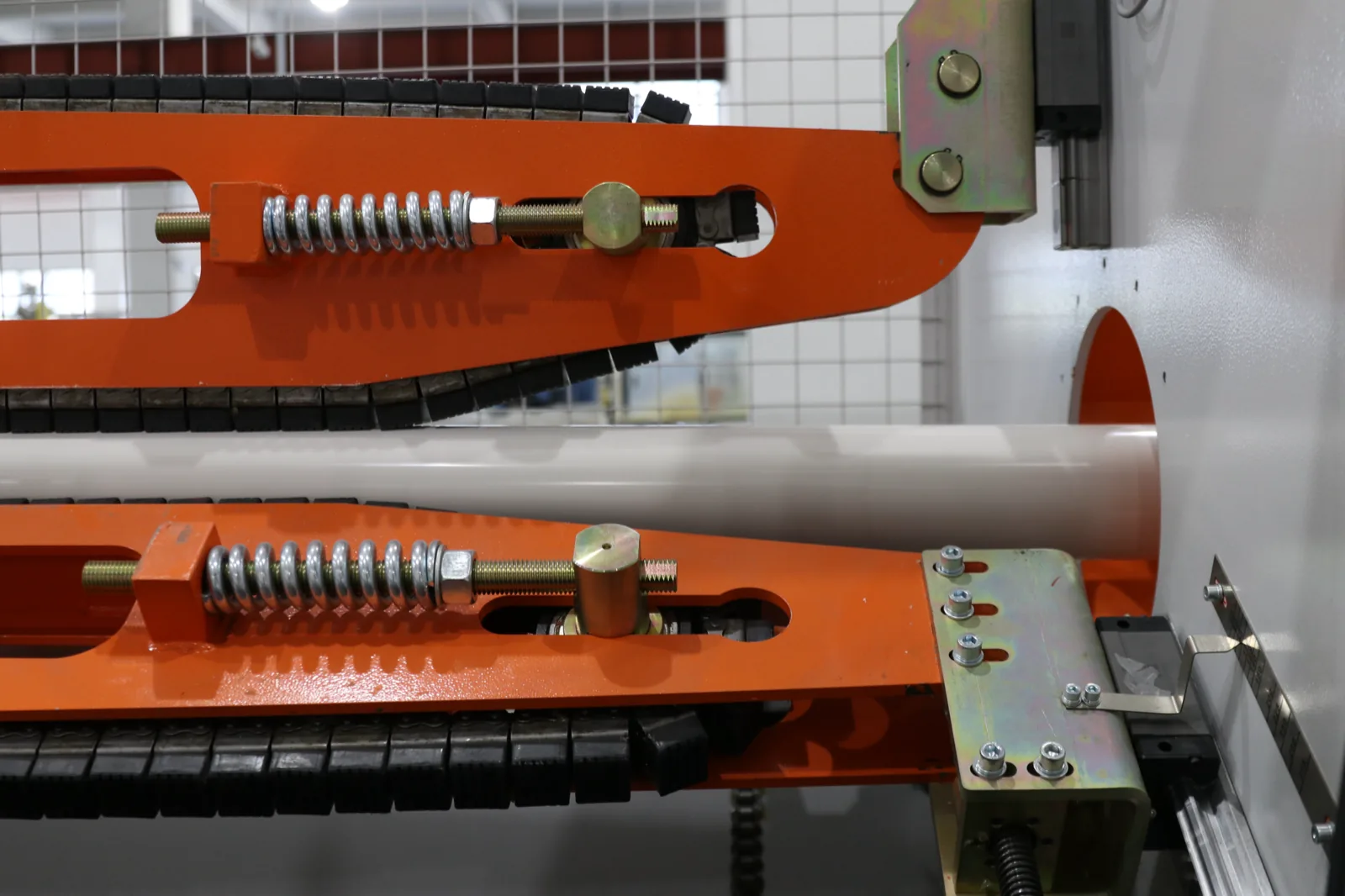
This detail separates a compensator that lasts from one that cracks a fitting in year three, and it is the least widely observed rule in this article.
PPFA describes the mechanism the offset relies on: “A pipe offset relieves thermal expansion forces by transforming it into a moderate bending stress. A compressive or tensile axial stress in a straight run of pipe may be relieved by transforming it to a bending stress at an offset.” The offset length acts as a cantilevered beam to the long pipe run; when the run grows by ΔL, the offset leg bends and absorbs the stress. [PPFA User Bulletin, p.6]
The critical placement rule follows directly: “It should be noted that in the figure, the bending in the offset begins at a guide and not at an anchor point. As already mentioned, some fittings have relatively low tolerance to bending, particularly when the bending is repetitive which can lower strength through fatigue. Accordingly, connections of offsets to rigidly held fittings should be isolated from bending stresses by means of guides, clamps or other devices.” [PPFA User Bulletin, p.6]
Read that as a failure mechanism rather than a preference. If the bending starts at the fitting, every thermal cycle works a joint that was never designed for repetitive flexure. A chilled water system cycles daily and often seasonally, so the cycle count accumulates fast. The joint does not fail on day one — it fatigues. That delay is precisely why the rule gets ignored: nothing goes wrong during commissioning.
The practical instruction: a guide belongs between the anchor or fitting and the start of the bending leg, positioned so the leg is free to flex beyond it and the fitting is shielded from that flexure.
What we could not verify, and will not publish. A guide-spacing rule stating “first guide at 4 pipe diameters from the loop elbow, second guide at 14 diameters from the first” circulates widely and is commonly attributed to EJMA (Expansion Joint Manufacturers Association). We could not verify it in any primary source. We searched the PPFA bulletin, both Georg Fischer handbooks and the DST expansion guide — none contains a 4D/14D rule — and the EJMA standard itself is paywalled and was not opened. The rule also originates in metal-pipe and expansion-bellows practice, and its applicability to plastic chilled water piping is unestablished. We are not publishing that number. If your specification needs it, buy the EJMA standard.
Similarly, we could not find a published numeric maximum guide interval for buckling restraint on long straight plastic runs. The Georg Fischer handbooks give bracket spacing for sagging under gravity load and state that guides must be loose-fitting, but give no maximum guide interval; PPFA does not give one either. Since plastic pipe in compression deflects laterally rather than generating thrust — PPFA confirms that mechanism explicitly — a guide-interval rule almost certainly exists in some manufacturer literature, but we could not verify one and will not invent it. IFANNova guide-spacing recommendations: Coming soon.
A bellows or slip-type expansion joint looks like a compact substitute for a loop. On plastic pipe it generally is not, and PPFA gives the mechanism:
“When subjected to a compressive thrust plastic pipe, because of its relatively lower stiffness as compared to metal pipe, tends to deflect laterally rather than generate the reactive thrust necessary to close the expansion joint.” [PPFA User Bulletin, pp.5–6]
That is the same low-modulus property that makes plastic anchors cheap, turning against you. The joint needs force to close it; the pipe buckles sideways instead of supplying that force. Two further points from the same source: “In pressure service expansion joints readily expand, but do not always fully return, which causes further pipe deflection,” and “because expansion joints do not transmit thrust they need to be used with carefully located thrust absorbing pipe anchors.” Expansion joints are commercially available principally for PVC and CPVC up to about nominal size 12. [PPFA User Bulletin, pp.5–6]
The practical reading: on plastic chilled water pipe, geometry (loops, offsets, direction changes) is the primary compensation method. A mechanical joint is the exception, and it requires more anchor design rather than less.
Everything above sizes a compensator for a given ΔL. There is a way to attack ΔL itself, and on PP-R it is dramatic.
Two manufacturers publish the fibre effect independently of each other:
| Source | Pipe | Coefficient (mm/mK) |
|---|---|---|
| Aquatherm | green faser fibre-composite pipe | 0.035 |
| Aquatherm | non-faser pipe | 0.03 |
| Aquatechnik | plain Fusion-Tech PP-R | 0.150 |
| Aquatechnik | faser fibre-reinforced pipe | 0.035 |
[Aquatherm FAQ, thermal expansion of PP-R; Aquatechnik NA, Design and Installation Manual, Table 22, p.32] The Aquatechnik pair are the two numbers that drive the compensation geometry below. The rest of that manual’s comparison set (PE-HD, PE-RT, PE-X, copper, steel) covers the same ground as the pillar’s material table and is not reproduced here.
A unit-label error in that table, flagged so you do not propagate it. Table 22 prints its units as “α = in/(ft·°F)”, but the values are in mm/(m·K). The proof is internal to the document: reading 0.150 as in/ft·°F would give 22.5 mm/mK, physically absurd for PP-R; the listed steel (0.011), copper (0.0170) and PE-HD (0.130) match the accepted mm/mK values for those materials exactly; and the manual’s own product datasheets give plain pipe as 0.001008 in/ft·°F, which converts to 0.151 mm/mK, matching the table’s 0.150. Cite the values, not the printed unit label. [Aquatechnik NA manual, Table 22 p.32, cross-checked against product datasheets in the same document]
Those same datasheets independently confirm the fibre effect:
| Pipe | Datasheet value (in/ft·°F) | Converted (mm/mK) |
|---|---|---|
| Plain pipe | 0.001008 | 0.151 |
| Fibre pipe | 0.0002367 | 0.0355 |
That is a 76.5% reduction, consistent with the manual’s “up to 70%” claim and in agreement with Aquatherm’s 0.035 mm/mK from an entirely separate manufacturer. [Aquatechnik NA manual, Table 22 p.32 and product datasheets pp.24–30]
Worked from the verified coefficients above, for a 100 ft run at ΔT = 25 °F, then fed into Aquatechnik’s LB = C·√(D·ΔL) on 2.48 in OD pipe:
| Pipe | α (in/in·°F) | Movement over the run | Constant C | Leg LB (in) |
|---|---|---|---|---|
| Plain PP-R | 8.4 × 10⁻⁵ | 2.52 in (64 mm) | 14 | 35.0 |
| Fibre PP-R | 1.97 × 10⁻⁵ | 0.59 in (15 mm) | 16 | 19.4 |
The movement reduction is a factor of 4.3. [Computed from Aquatechnik NA Design and Installation Manual verified coefficients (Table 22 and datasheets) and formula LB = C·√(D·ΔL) (Table 27)]
Fibre reinforcement cuts the required bending-arm length by a factor of 35.0 / 19.4 = 1.81, a 45% reduction, even though its C constant is higher. Two effects work against the 4.3× reduction in ΔL. First, the leg scales with √ΔL, not ΔL, so a 4.3× movement reduction buys only √4.3 = 2.07× on length. Second, the higher constant gives back part of that: 2.07 × (14/16) = 1.81. Both steps are reproducible from LB = C·√(D·ΔL) with the figures above. This is still the highest-leverage decision available on a congested chilled water route — it shortens every compensator on the drawing at once, without touching anchor design.
IFANNova does not currently offer a fibre-composite PP-R line. Our PPR PN20 range is series 1103 in 20/25/32 mm only, with 75 fitting items in series 1138 (per our catalogue). If your design depends on fibre-reinforced PP-R to make the expansion geometry fit, that is a genuine reason to specify elsewhere, and we would rather say so than have you discover it at installation.
Not every run needs a loop, and over-detailing has its own cost. Aquatechnik gives two thresholds:
“For installations with many direction or level changes and with short straight sections (<100 ft.), the effects of expansion may be ignored, securing the pipe with only fixed points.” And for concealed pipe: “When concealing pipe, the effects of linear thermal expansion are not considered, as the pipe is considered to be self-compensating.” Omega compensators or flex-curve direction changes are required for long straight exposed runs with external supports — basements, boiler rooms, power stations. [Aquatechnik NA Design and Installation Manual, installation section]
Both thresholds are Aquatechnik’s, for Aquatechnik pipe. They are not general engineering law, and the <100 ft figure carries an implicit condition — “many direction or level changes” — that is doing as much work as the length limit. A 90 ft dead-straight run between two anchors does not qualify.
This is where IFANNova’s actual product range matters to the answer. Our pressure-pipe ceiling is Φ110 — UPVC 806 PN16 and HDPE PN16, both Φ20–Φ110; PPR PN20 stops at 32 mm. Our PVC 902 line reaches Φ160 in the 1902 fittings only — the 902 pipe stops at Φ110 — and 902 is non-pressure drainage and is excluded from chilled water pressure duty (per our catalogue). We cannot supply DN150–400 chilled water mains, and we do not claim to. The runs our products serve are branch and terminal-level: short, frequently offset, and routed through ceiling voids and risers rather than in long straight plant-room mains. That is exactly the geometry Aquatechnik’s threshold describes as self-compensating. In practice, a large fraction of branch-level chilled water piping in our size range will be compensated by the route’s own direction changes and will need fixed points more than loops.
Our supplied ranges, for reference: UPVC 806 PN16 from Φ20–110 with 203 fitting items in series 1806; HDPE PN16 marked to DIN 8077/8078 (per our catalogue) from Φ20–110 with series 603/604 weld-free compression fittings; PVC 902 pipe Φ32–110 with 1902 fittings Φ32–160, non-pressure drainage — not for chilled water pressure duty; PEX series 2114/2121 in 16–32 mm; brass series 2405 (per our catalogue). Note from PPFA’s material table that PEX and PE-RT sit at the high end of the coefficient range (9.5 × 10⁻⁵ and 9.0–12.0 × 10⁻⁵ in/in·°F respectively) while PVC sits at the low end (3.5 × 10⁻⁵). [PPFA User Bulletin, p.3] Within our own range, the PVC-based lines are the low-movement option for any run long enough for expansion to govern.
One consequence is specific to cold service and does not appear in general expansion literature. On a chilled line, every point where the pipe is clamped, guided, or passes through structure is a potential interruption of the insulation vapour barrier — and on cold pipe, vapour drive is inward and continuous.
The penalty is quantified: “For every 1% of moisture gain, there is a 7.5% loss in thermal efficiency.” Condensation “will dramatically accelerate pipe deterioration, create mold on pipe insulation, and possibly damage insulation throughout the system.” The stated requirement is “to maintain an unbroken vapor barrier on pipe, specialty valves, and equipment.” [Insulation Outlook (National Insulation Association), “Chill Out: Maintaining Integrity of Chilled-Water Systems”]
Be precise about what that source does and does not say: it addresses vapour barrier integrity on chilled water systems generally and does not specifically address pipe movement at supports, anchors and guides. The connection between the two is our engineering judgement, stated as such: a sliding guide is by definition a location where the pipe moves relative to the support, and a moving interface is harder to keep vapour-tight than a static one. A loop adds further penetrations at each guide. The compensation geometry you draw creates the vapour barrier detailing burden that follows, and the two should be designed together rather than sequentially.
The general insulation and condensation treatment is in the pillar guide. IFANNova insulation specifications: Coming soon.
Every formula, constant and coefficient in this article is attributed to a third-party manufacturer or industry association, with the document and page cited. None of it is IFANNova data. We publish no expansion coefficient, no flexible-section constant, no guide-spacing table and no slide-guide friction figure of our own. Those are Coming soon, and we would rather label the gap than fill it with a borrowed number that carries someone else’s stress basis.
IFANNova is a French brand. Manufacturing is by Zhuji Fengfan Piping in Zhuji, Zhejiang, with 30+ years of operation, 1000+ employees, supply to 118+ countries and a 120,000 m² facility. Certifications on record: SKZ, CE, WRAS, DVGW, SGS, ISO 9001 and ISO 14001; certificate numbers are Coming soon.
The size ceiling is the honest constraint on everything above. With a pressure-pipe ceiling of Φ110 (UPVC 806 and HDPE, both PN16) and 32 mm on PPR, we supply branch and terminal chilled water piping — not DN150–400 mains. If your expansion problem is a 200 m straight run of DN300 in a district cooling plant room, the engineering in this article still applies, but we are not your supplier for that line. For branch-level chilled water piping within our range, and for the fittings that go with it, talk to us.
Background on material selection, sizing constraints, insulation and certification is in the chilled water piping pillar guide.
Why the vapour barrier — not insulation thickness — decides whether chilled water insulation survives.
The chilled water failure mode that is not a leak: how ceiling-void condensation forms, how to tell it from a leak, and what actually prevents it.
Where HDPE fits in HVAC: condenser water loops and buried chilled water runs, with pressure derating, burial deflection and jointing choices.
