This is a counting article. Material selection, sizing constraints, insulation theory and the standards landscape live on our pillar page, chilled water piping. None of it is repeated here. What follows is the layer below: you have a floor plate, a riser, and a count of terminal units, and somebody has to turn that into a bill of materials that will not stop the job. Every component named below is a purchase-order line item that has to be counted correctly and arrive in the right pressure class.
A chilled water branch is not stopped by pipe. Pipe arrives in bulk and gets cut on site. Jobs stop for a missing reducing tee, a strainer with the wrong mesh, or a union rated below the system test pressure. Those are take-off failures, not design failures. They are avoidable by counting more carefully than “one valve package per FCU.”
Before you can count anything, you need to know what one terminal branch contains. The most useful published answer is a manufacturer’s factory piping package — a complete, priced, code-defined list rather than a sketch. Krueger’s piping packages for chilled and hot water fan coil units, blower coil units and AHUs comprise, in code combinations: a 2-way or 3-way control valve; manual ball isolation valves with adjustable memory stop (BVMS); automatic fixed flow control (FC); a Y-strainer (Y-STR) with Y-strainer cleanout (Y-CO); pressure/temperature (P/T) test ports; unions; and a 1/4 in. bleed line on 2-pipe changeover units (Krueger, Piping Packages for Chilled and Hot Water Fan Coil Units, Blower Coil Units, and AHUs).
Two things in that list change how you count. First, the isolation valves double as balancing devices: “All ball isolation valves are furnished with an adjustable memory stop feature and may be used as a balancing valve” (Krueger). Second, the P/T ports are positional. They “are located to monitor the pressure and temperature across the coil” (Krueger) — a pair per coil, not one per branch.
Treat that as the checklist skeleton. In our experience — opinion, not a sourced figure — the components most often dropped from a first-pass take-off are the strainer cleanout, the P/T ports, the bleed line on changeover units, and the insulation of the valve package itself. The last is discussed at the end, because it has a documented scope gap behind it.
A caution before any arithmetic: there is no industry-standard published count of fittings per FCU. We looked for one from a standards body, an association, or a manufacturer and found nothing citable. Only unsourced estimating blogs publish such numbers. So we will not invent “N elbows per unit.” What can be counted honestly is component classes and the rules that change their quantity.
| Component | What drives the count | The trap |
|---|---|---|
| Isolation valves | Supply and return per coil | 4-pipe units have two coils — count both circuits |
| Control valve | One per controlled coil | 3-way adds a bypass leg and its fittings |
| Y-strainer + cleanout | One per supply branch | Cleanout is a separate line item, not included by default |
| P/T test ports | Across the coil, so in pairs | Counted as one per branch instead of two |
| Unions | Disconnect points for coil removal | Deleted entirely when flex hoses are used — see below |
| Balancing device | Depends on reverse-return vs direct-return | Reverse-return may remove it; PICV replaces several items |
| Bleed line | 2-pipe changeover units only | Omitted because it is not on the standard package drawing |
This is the most instructive number in the branch package. It shows why “one valve package” is not a specification. The components do not share a pressure rating. Per Krueger’s control device legend: manual ball valve with memory stop (BVMS) 600 psig at 325 °F (163 °C); fixed flow control (FC) 600 psig; Y-strainer 600 psig; Y-strainer cleanout 600 psig; P/T test port 400 psig; control valve 450 psig; fixed cartridge flow control with P/T ports (FCN/FCS) 230 psig; and the union — 125 psig standard, with 600 psig available on request.
| Branch component (Krueger legend) | Pressure rating |
|---|---|
| Manual ball valve w/ memory stop (BVMS) | 600 psig, 325 °F (163 °C) |
| Fixed flow control (FC) | 600 psig |
| Y-strainer (Y-STR) | 600 psig |
| Y-strainer cleanout (Y-CO) | 600 psig |
| Control valve | 450 psig |
| P/T test port | 400 psig |
| Fixed cartridge flow control w/ PT ports (FCN/FCS) | 230 psig |
| Union (standard) | 125 psig (600 psig available on request) |
Read the spread: 125 against 600 psig. A branch assembled from default parts is a 125 psig assembly whatever the rest is rated for. A chain is rated at its weakest component. On a tall building, static head climbs floor by floor and hydrostatic test pressure exceeds working pressure. This is the item that fails the test, and it fails after the ceiling is closed.
The take-off action takes one line: write the required union pressure class on the schedule, and confirm it is the upgraded class rather than the default. The 600 psig union is “available on request” (Krueger) — you will not get it unless the order says so. A take-off that lists “union” without a class has already chosen wrong by default.
Here the take-off quantity of an item legitimately becomes zero, and double-counting is the more common error. Krueger states that on KVP units, “All KVP units include two flexible stainless steel braided hoses and ball isolation valves per coil. This hose/valve combination provides a ‘union’ type connection to allow coil removal.” Separately: “When ordered, unions are installed at the water coil on all fan coil units except KVP. Unions must be ordered on both coils of 4-pipe units. Unions are not available separately.”
Three counting rules fall out of that text:
If you specify flex hoses, specify them properly. The fire performance data is what gets omitted. The Krueger 18 in. Flexible Hose Kit (FH) is EPDM inner lined, Kevlar-reinforced, with a stainless steel outer covering; flow rates 0.5 to 12.0 GPM; rated 375 psig at 250 °F (121 °C) with 450 psig test pressure; minimum burst pressure 1500 psi; flame spread not greater than 25 per UL 723 and smoke development not greater than 50 per UL 723; available in 1/2 in. size only. The integral ball valve with memory stop is full port brass, stainless ball, Teflon seats, two Viton O-ring stem seals, 600 psig WOG, 325 °F (163 °C), Cv 20 (Krueger).
Two of those are take-off constraints, not trivia. “Available in 1/2 in. size only” means the flex-hose strategy does not scale up the branch schedule. Larger terminals need a different disconnect detail, and your BOM now has two detail types. And the UL 723 flame spread and smoke development figures are exactly what a plenum-space submittal gets rejected for lacking. Both belong on the schedule line, not in a note.
Braided connectors carry installation constraints that affect the length you order and the space you must reserve. Overall length must not force the hose into tension, compression, torsion, or a bend tighter than the minimum bend radius. Braided connectors are designed for lateral movement only and cannot handle axial movement unless combined into a loop assembly. Locating a connector immediately downstream of an elbow may not reduce vibration if the waves are torsional (Unisource Manufacturing, Stainless Steel Braided Pump Connectors). For the larger connectors used at plant rather than terminal level, Unisource Series 401 threaded flex connectors are rated 250–990 psig depending on size (1/2 in.–4 in.), Series 402 flanged 150–455 psig (1-1/2 in.–14 in.), and Series 401-L longer-length connectors provide a minimum of 2 in. permanent lateral offset.
The counting consequence: if the hose cannot be installed in tension or torsion, length is a designed dimension. A floor with varying coil offsets may need more than one hose length on the BOM. “18 in. hose × unit count” is an assumption, not a take-off.
A strainer left unqualified on a schedule is a decision handed to whoever fills the order. It has a factory default, and the default may not be what the design assumed: “11M Screwed Strainers up to 2″ Size Normally Furnished with 20 Mesh Screens” (Mueller Steam Specialty / Watts, Screen and Basket Facts). Small screwed Y-strainers — what a terminal branch uses — arrive at 20 mesh unless the order says otherwise.
What 20 mesh means, and what the alternatives cost in open area, per Mueller Steam Specialty:
| Mesh | Openings | Wire dia. | Open area |
|---|---|---|---|
| 20 | 1/32 in. | 0.014 in. | 52% |
| 30 | 1/50 in. | 0.012 in. | 41% |
| 40 | 1/64 in. | 0.010 in. | 36% |
| 60 | 0.009 in. | 0.0075 in. | 30.5% |
| 80 | 0.007 in. | 0.0055 in. | 31.4% |
| 100 | 0.005 in. | 0.0045 in. | 30.3% |
Mesh-to-micron for the common default: 20 mesh = 0.0331 in. = 841 µm = 0.841 mm (Mueller Steam Specialty).
A warning if you are cross-checking two vendors’ quotes. Open area is not a universal property of a mesh number. Islip Flow Controls publishes materially different figures for the same nominal meshes: 20 mesh = 0.035 in. openings, 49% open area; 30 mesh = 0.022 in., 45%; 40 mesh = 0.016 in., 41%; 60 mesh = 0.010 in., 38%; 80 mesh = 0.008 in., 36%; 100 mesh = 0.006 in., 30% (Islip Flow Controls, Engineering Data: Screen Openings for Y-Strainers). Two vendors, same mesh number: 49% versus 52% open area at 20 mesh, 41% versus 36% at 40 mesh. If your pressure-drop calculation assumed one and the delivered part is the other, the calculation moves. Compare the published data for the actual part, not the mesh number.
For perforated plate rather than mesh, Islip gives: 1/32 in. dia = 40% open area; 3/64 in. = 36%; 1/16 in. = 37%; 1/8 in. = 40%; 5/32 in. = 58%; 3/16 in. = 50%; 1/4 in. = 40%.
The instinct on a chilled water branch protecting a small control valve is to specify the finest mesh available. That instinct is documented as wrong: “As a general rule the specified level of filtration should be no smaller than half the size of the particle to be removed. If too fine a filtration is specified the pressure drop through the strainer will increase very rapidly, possibly causing damage to the basket [screen]” (Islip Flow Controls).
Note what that says. The consequence is not merely higher pump head. It is mechanical damage to the screen, which then passes debris downstream — the exact outcome the fine mesh was specified to prevent. The rule is a sizing rule: filtration no smaller than half the particle you are removing. Going finer buys nothing and risks the screen.
Mesh alone does not determine strainer behaviour. The governing quantity is the open area ratio: OAR = Free Area of Strainer Screen/Basket ÷ Cross-sectional Area of Pipeline, where Free Area = (surface area of the strainer screen/basket) × (percent open area of the perforated plate or mesh). It is expressed as a ratio such as 10:1, 4:1 or 1:1. The consequence is stated in terms of clogging: “As the strainer becomes clogged, the pressure drop increases and eventually blocks the flow” — and a lower ratio shortens the run before that happens, because “the higher the OAR, the longer you can run your strainer and the less time you spend cleaning it out” (FCX Performance, Open Area Ratios and Strainer Performance).
This is where the two vendor tables stop being trivia. Free Area is the product of screen surface area and percent open area, so a 5% difference in the published open-area figure propagates straight into the OAR and therefore into the maintenance interval. Two strainers with identical mesh numbers and identical connection sizes can have different screen surface areas, different open-area percentages, and different OARs.
If you are converting a catalogue pressure-drop curve to your actual screen, the correction factors are published. For sizes 1/4 in.–1-1/2 in., perforated plate: 60% open area = 0.45; 50% = 0.55; 40% = 0.7; 30% = 1.0; 20% = 1.15. Mesh-lined standard screens: 50% = 1.05; 40% = 1.05; 30% = 1.2. For sizes 2 in.–48 in., perforated: 60% = 0.65; 50% = 0.8; 40% = 1.0; 30% = 1.4; 20% = 2.15; mesh-lined: 50% = 1.05; 40% = 1.05; 30% = 1.2 (Screen Openings for Strainers — Engineering Data, screen correction factor chart).
Read the large-size perforated column: going from 40% to 20% open area multiplies the correction factor from 1.0 to 2.15. Halving the open area roughly doubles the pressure drop. That is the arithmetic behind the over-straining warning.
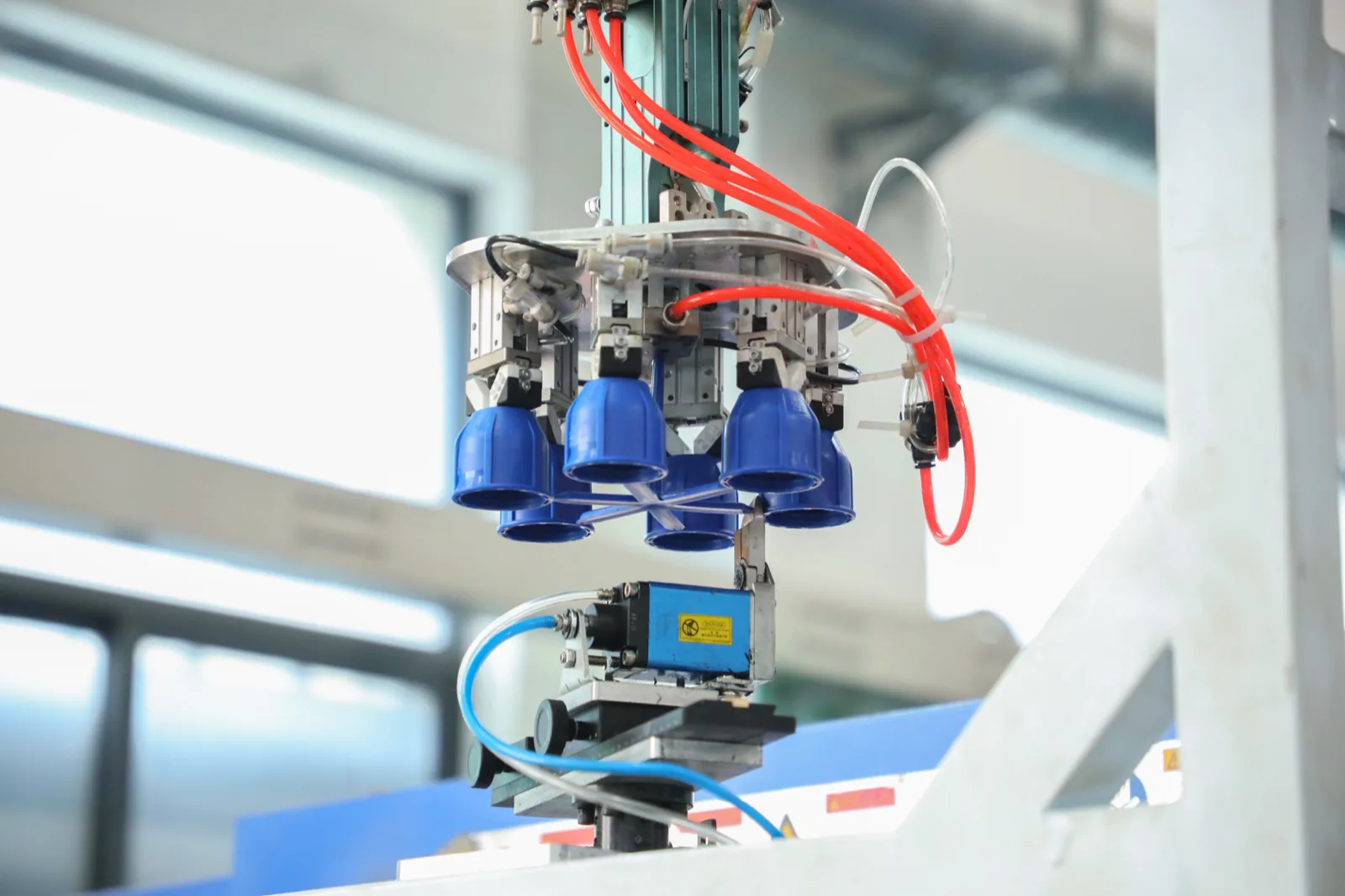
A control valve on the take-off in the right quantity and the wrong size produces a floor that cannot be balanced. Two published relationships govern this, and both are simple enough to run on every branch line of a schedule.
Authority determines whether a valve modulates or acts as an expensive on/off device. N = ΔPv / (ΔPc + ΔPv), where N is control valve authority (dimensionless, often expressed as a percentage), ΔPv is the pressure drop across the control valve fully open, and ΔPc is the pressure drop across the remaining circuit — pipes, fittings, strainer, isolation valve, DPCV and DRV. ΔPv is itself computed as ΔPv = (Q/Kvs)² (Flo Control Ltd, Valve Authority: Definition and Relevance, D. Taylor, 6 Oct 2020).
Note what is inside ΔPc: the strainer and the isolation valve. The strainer mesh decision from the previous section feeds directly into the authority calculation. These are not independent line items.
The published bands:
| Authority | Control quality |
|---|---|
| 0–25% | Unstable to fair control, low pressure drop |
| 25–50% | Fair to good control, reasonable pressure drop |
| 50–100% | Good to excellent control, high pressure drop |
“For practical purposes Control Valves are selected to have an authority of 35-75%… Normally a 50% authority is targeted, which will vary depending on the availability of the Control Valve Kvs values” (Flo Control Ltd).
Required flow coefficient, metric form: Kvr [m³/h] = 36 × Qc [l/s] / √ΔPc [kPa], where Kvr is the required valve flow coefficient, Qc the circuit or FCU flow rate in l/s, and ΔPc the circuit or FCU pressure drop in kPa (Flo Control Ltd).
Take an FCU at Qc = 0.1 l/s with ΔPc = 9 kPa. Then Kvr = 36 × 0.1 / √9 = 3.6 / 3.00 = 1.2 m³/h.
You cannot buy 1.2. Valves come only in a Renard series of Kvs steps: 0.25, 0.63, 1.00, 1.60, 2.5, 4.00, 6.30, 10, 16 (Flo Control Ltd). The real decision is which side of 1.2 to land on, and the two outcomes are not equivalent:
| Selection | ΔPv | Authority |
|---|---|---|
| Kvs 1.0 (below Kvr) | ((36×0.1)/1.0)² = 12.96 kPa | 12.96/(9+12.96) = 59.0% |
| Kvs 1.6 (above Kvr) | ((36×0.1)/1.6)² = 5.0625 kPa | 5.0625/(9+5.0625) = 36.0% |
Rounding rule for the two rows above: ΔPv is carried at full precision into the authority fraction, and only the final percentage is rounded, to one decimal place. Rounding ΔPv first — 12.96 down to 12.9, or 5.0625 down to 5.06 — moves the answer in the first decimal of the authority and is the kind of silent truncation that makes two engineers’ schedules disagree about the same valve. Both rows are reproducible from the formulas exactly as printed: ΔPv = (Q/Kvs)² with Q = 36 × 0.1 = 3.6, then N = ΔPv / (ΔPc + ΔPv) with ΔPc = 9 kPa.
Both land inside the 35–75% practical band, so both are defensible. But they carry different pump-head consequences — 12.96 versus 5.0625 kPa per branch — and multiplied across every terminal on a floor, that difference is a real number in the plant selection. This is the calculation that “one control valve per FCU” hides. Run it per branch type, not per project.
A control valve must also shut against the differential across it. The published limits are size-dependent and not monotonic. Per Krueger’s guide specification: “Maximum entering water temperature on the control valve is 200°F [93°C], and maximum close-off pressure is 40 PSIG (1/2″), 20 PSIG (3/4″), 17 PSIG (1″), 50 PSIG (1-1/4″), 50 PSIG (1-1/2″). Maximum operating pressure shall be 450 PSIG.” A high close-off option exists for 2-way valves at 125 psig for 1/2 in. and 3/4 in.
Read the sequence: 40, 20, 17, 50, 50 psig. The 1 in. valve has the lowest close-off capability of the five, less than half the 1/2 in. valve. Anyone assuming “bigger valve, more capable” has the relationship backwards. On a high-rise where branch differential pressure rises toward the lower floors, this is where valves fail to shut and coils cannot be isolated.
Typical 2-way 2-position paddle valve Cv values: 1/2 in. = 2.5; 3/4 in. = 5.0; 1 in. = 8.0 (Krueger). The same non-monotonic warning applies to the isolation valves: Krueger BVMS Cv is 17 at 1/2 in., 32 at 3/4 in., and 27 at 1 in. The 1 in. valve has a lower Cv than the 3/4 in. All BVMS sizes are brass body, hard chrome plated ball, Teflon seats, sweat connection, 600 psig, 325 °F (163 °C); the stem seal differs by size — two Viton O-rings on 1/2 in., Teflon on 3/4 in. and 1 in. (Krueger).
Practical take-off note: if your schedule sorts by size and interpolates Cv or close-off between rows, it will produce wrong numbers. These are tabulated values, not curves.
For incompressible fluids, Q = Cv × √ΔP, equivalently Q = Kv × √ΔP in metric. Cv is defined as the volume of water in US GPM at 60 °F (15.6 °C) that flows through a fully open valve with a pressure differential of 1 psi across the valve. Conversion: Kv ≈ 0.86 × Cv, or Cv ≈ 1.16 × Kv — the difference arising because the metric and imperial systems use different reference pressures, 1 bar versus 1 psi (Pipe Flow, Cv and Kv Flow Coefficients).
The size of the error depends on which way you got it wrong, and the two directions are not the same number. Taking a Cv figure as though it were a Kv overstates the coefficient: the correct value is 0.86 × Cv, so the unconverted number is high by 14% of itself. Taking a Kv figure as though it were a Cv understates it: the correct value is 1.16 × Kv, so the unconverted number is low by 16% relative to the Kv it should have become. Quoting one percentage for both directions is itself a common schedule error — 14% and 16% are the same conversion read from opposite ends.
On a mixed-source take-off — European valves, American terminal units — Cv and Kv figures land in the same column of the same spreadsheet. A 14–16% error in flow coefficient, depending on direction, is large enough to move a valve selection one full step in the Renard series, which per the worked example above moves authority from 59.0% to 36.0%. Label the units in the column header.
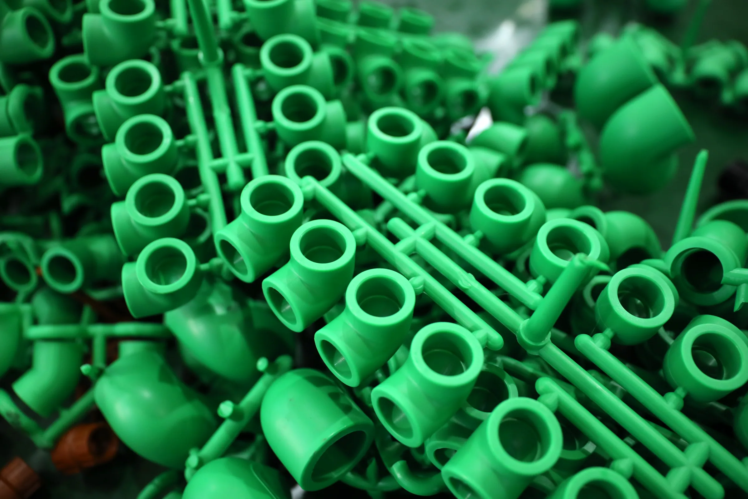
The number of balancing devices per floor is not fixed. It is set by a decision made upstream of the branch, and it is one of the largest legitimate swings in a branch take-off.
ASHRAE defines a reverse return piping system as a “Two-pipe system in which the heat transfer medium supplied to the first load is the last returned to the heat transfer equipment. A system in which the water return piping from terminal units is sized to provide equal lengths for balanced flow rates” (ASHRAE Terminology). Because the layout itself equalises circuit lengths, the balancing burden that would otherwise fall on per-branch devices is partly absorbed by the pipe routing — at the cost of additional return pipe. The take-off must reflect that trade: more pipe and potentially fewer devices, versus less pipe and more devices.
Where fixed flow limiting is used, the device has its own schedule requirements. Krueger’s automatic fixed flow control (FC) is a pressure-compensated device limiting GPM through the coil, and “desired GPM must be specified at time of order” — a copper body, sweat connection, 225 °F (107 °C) part. Pressure rating is 600 psig for Device A (up to 8.0 GPM, changeable flow cartridge) and 522 psig for Device B (flows above 8.0 GPM). GPM ranges by package diameter: 1/2 in. = 0.5–9.0 GPM; 3/4 in. = 3.0–12.0 GPM; 1 in. = 5.0–20.0 GPM (Krueger).
“Desired GPM must be specified at time of order” is a take-off requirement disguised as a specification note. A schedule listing “FC, 1/2 in.” is incomplete and will be queried or guessed. Every FC line needs a GPM value against it. Note the overlapping ranges too: 3.0–8.0 GPM can be served by either the 1/2 in. or the 3/4 in. package, so the choice is yours to make and to record.
A pressure independent control valve changes the shape of the branch BOM rather than substituting one part. Krueger: “PICV is a combination of three main components; a pressure regulator, a regulating valve, and a control valve. The pressure regulator adjusts the system for pressure fluctuation, while the regulating valve sets the maximum flow. The control valve modulates between the minimum and maximum flow in response to the configured flow rate.” Specifications: nominal sizes 1/2 in. and 3/4 in.; forged brass body; NPT connection; EPDM O-ring seals; 360 psig; 250 °F (121 °C); differential pressure range 3–87 psig.
Caleffi frames the substitution in take-off terms: a PICV provides “the functional equivalent of either a zone valve paired with an automatic balancing valve, or a static balancing valve paired with a modulating flow control valve.” The PICV line replaces two lines, and the connections and fittings between those two devices disappear with them.
It also removes the entire authority calculation: “With the emergence of the variable flow system and the Pressure Independent Control Valve (PICV Valve) authority calculations are almost a thing of the past because the PICV Valve has 100% valve authority with a constant minimum differential pressure requirement to make them function… A PICV Valve combines the control, balancing & differential pressure control functions in one valve housing, eliminating the need for DPCVs and DRVs in the system” (Flo Control Ltd).
The cost is head, and it must be budgeted rather than discovered. Caleffi: “the minimum differential pressure varies from 3.6 to 4.4 psi depending on the flow rate setting” (approximately 25–30 kPa), with an upper operating limit of 60 psi (approximately 414 kPa). Worked instance: for 3 gpm, a 145…3G5 valve at setting 9 requires a minimum of 4.1 psi (approximately 28 kPa) across the valve itself.
Compare that against the worked authority example above, where a conventional Kvs 1.6 selection produced 5.0625 kPa across the valve. The PICV’s ~28 kPa minimum is roughly five times higher. That is not an argument against PICVs. It is the pump head those deleted line items were costing you elsewhere, now made explicit and located in one component. Take-off consequence: switch to PICVs late and the pump selection has to be revisited even though the pipe schedule did not change. Note also the 1/2 in. and 3/4 in. size limit — the PICV strategy does not cover every terminal on a mixed floor.
This omission has the worst consequence-to-visibility ratio in the take-off, and it is documented rather than anecdotal. Krueger General Note 14: “Some piping packages may extend beyond the unit drain pan and/or factory auxiliary drip pan. Requirements for field furnished and installed valve package and piping insulation must be determined by others on an individual application basis.”
“By others” means it is on nobody’s BOM until someone puts it there. The factory ships the valve package; the insulation contractor prices the pipe; the valve package geometry — a cluster of irregular shapes with a strainer, ports and a valve body — falls between the two scopes. Our pillar page covers thickness determination and the ASHRAE 90.1 tables, so we will not restate them. The point here is that the quantity is a separate take-off line with a defined owner.
Two facts should govern how that line is written. First, the code minimum is not the design answer. ASHRAE 90.1’s tabulated thicknesses carry the footnote: “These thicknesses are based on energy efficiency considerations only. Additional insulation is sometimes required relative to safety issues/surface temperature.” Insulation industry guidance is more direct — the 90.1 thicknesses “were determined for energy conservation, not for condensation control, which often requires thicknesses greater than 1 in., particularly on pipes running through unconditioned spaces” (Insulation Outlook / NIA). A ceiling void above a chilled water branch is very often exactly such a space.
Second, the vapour retarder is a specified line item with a number attached. Jacket/vapour retarder material “should be used that provides a 0.02 perm-inch rating (as per ASHRAE 2013 Handbook of Fundamentals, Chapter 23), is more puncture resistant, and is completely adhered to the insulation,” with the design principle being to keep the surface temperature of the insulation system above the dew point (Insulation Outlook / NIA). “Completely adhered” is an installation requirement — labour, not just material, belongs in the take-off.
The failure mechanism is a runaway, and it sits at the components this article has been counting. “Once the moisture penetrates the insulation, it reduces the thermal conductivity of the insulation, which results in condensation being formed under less severe conditions and before long, the insulation is waterlogged.” Damage at fittings — tees, elbows, and valves — “is the worst case scenario as it is hardest to detect and most difficult to remedy.” Corrosion under insulation (CUI) occurs when water vapour penetrates and reaches the metallic pipe surface, where it becomes trapped and acts as a constant source of deterioration (Insulation Outlook / NIA).
Follow the loop: a vapour retarder breach admits moisture; wetted insulation conducts better; better conduction drops the surface temperature; the lower surface temperature causes condensation under milder conditions; that adds more moisture. It does not stabilise. And it is worst at the valve package, where the geometry is complex, the retarder is hardest to seal continuously, and — per the scope note above — the work most likely fell between two contracts.
Take-off action: schedule the fitting and valve-package insulation as its own quantity with its own labour line, name the perm rating, and confirm the scope owner in writing.
Small notes, disproportionate effect on a purchase order:
Being precise about this is more useful to a specifier than a broad claim. IFANNova is a French brand; the products are manufactured by Zhuji Fengfan Piping in Zhuji, Zhejiang. The manufacturing base is 30+ years old, 1000+ employees, exporting to 118+ countries from a 120,000 m² facility. We do not represent the products as made in France.
The ceiling, stated first. Our pressure-pipe ceiling is Φ110 — UPVC 806 PN16 and HDPE PN16, both Φ20–Φ110; PPR PN20 stops at 32 mm. Our PVC 902 line reaches Φ160 in the 1902 fittings only — the 902 pipe stops at Φ110 — and 902 is non-pressure drainage and is excluded from chilled water pressure duty (per our catalogue), so it does not raise the pressure-pipe ceiling. We cannot supply DN150–DN400 mains. If your floor take-off includes the riser or the floor header at those diameters, that is not our scope, and we will say so at enquiry rather than at delivery.
Where we do fit is the terminal branch layer this article is about — the run from the floor header out to the terminal units, at Φ110 and below in pressure pipe.
| Series | Range | Fitting inventory | Relevance to a branch take-off |
|---|---|---|---|
| PPR PN20 (1103 pipe / 1138 fittings) | 20 / 25 / 32 mm only | 1138: 75 items (per our catalogue) | Small terminal drops only; no capability above 32 mm |
| UPVC 806 PN16 (1806 fittings) | Φ20–Φ110 | 1806: 203 items (per our catalogue) | Widest fitting inventory we hold; the broadest branch coverage |
| HDPE PN16, marked DIN 8077/8078 per our catalogue (603 / 604) | Φ20–Φ110 | 603 / 604 compression, no-weld (per our catalogue) | No hot work, no fusion machine calibration — spanner assembly |
| Brass 2405 | 1/4 in.–1 in. | 2405 fittings and brass valves (per our catalogue) | Threaded transitions at terminal connections |
| PEX 2114 / 2121 | 16–32 mm | (per our catalogue) | Small-bore terminal work |
| PVC 902 drainage | Pipe Φ32–Φ110; 1902 fittings Φ32–Φ160 | (per our catalogue) | Non-pressure drainage — condensate only, excluded from chilled water pressure duty |
The item counts above — 1138 at 75 items, 1806 at 203 items — are the honest measure of what a branch take-off can be filled from in one order. The 1806 UPVC inventory at 203 items most often absorbs a full terminal branch schedule without a second supplier.
Certifications on record: SKZ, CE, WRAS, DVGW, SGS, ISO 9001, ISO 14001. Certificate numbers: Coming soon. If your submittal requires certificate numbers rather than certification names, ask before you schedule the submittal date.
What we do not publish, stated so you do not have to discover it:
Offered as a working method based on the sourced constraints above, not as a standard. No standards body publishes a per-floor branch count, and we found none to cite.
If your branch schedule sits at Φ110 and below in pressure pipe, send it with diameters, series preference and quantities. We will tell you what our 1806 (203 items), 1138 (75 items), 603/604 and 2405 inventories cover and what they do not. We will identify the gaps rather than quote around them. For pressure pipe above Φ110, or above 32 mm in PPR, we are not your supplier and we will say so at the enquiry stage; our only Φ160 item is a 1902 non-pressure drainage fitting, not a pipe.
Primary, primary-secondary and variable-flow chilled water loops compared — and which layer of the system a branch pipe supplier actually serves.
Expansion loops, anchors and guides for plastic chilled water pipe: how to size the offset leg, where to fix, and the engineering cost of choosing plastic.
Why the vapour barrier — not insulation thickness — decides whether chilled water insulation survives.
