Our chilled water piping guide covers materials, sizing constraints, insulation and standards. It does not tell you where in the plant a given pipe belongs — and that omission causes real procurement errors. When a chilled water enquiry reaches us, the first question back is which circuit the pipe sits in, because the answer decides whether we can supply it at all. This page covers loop architecture: what separates a primary circuit from a secondary one, the geometry rules governing the junction between them, the failure modes when those rules are broken, and which layer our Φ110 pressure-pipe ceiling actually serves.

In a primary-secondary plant, the plant is split into two hydraulically independent circuits joined by a neutral bridge, usually called the decoupler or common pipe. Primary pumps are constant-volume and low-head, sized only for the evaporator and primary-loop friction. Secondary pumps are sized only for the distribution loop pressure drop. The two are joined by a neutral bridge of two tees connected by a decoupling pipe designed for negligible pressure drop at design flow (PDHonline Course M328, HVAC Chilled Water Distribution, A. Bhatia PE, pp. 13–14).
The reason this works is worth quoting verbatim, because almost every informal explanation garbles it: “Primary-secondary pumping is based on a simple fact that when two circuits are interconnected, flow in one will NOT cause flow in the other if the pressure drop in the piping common to both is eliminated” (PDHonline M328, p. 26).
Hydraulic independence is therefore not a property of the pumps, valves or controls. It is a property of one short piece of pipe and its pressure drop. Get that pipe’s diameter or length wrong and the two circuits stop being independent — no control strategy recovers it.
The architecture exists for a regulatory reason. ASHRAE/IES Standard 90.1-1989 required that “all HVAC hydronic systems having a total pump system power exceeding 10 hp must be capable to flow at 50 % of design value or less” (PDHonline M328, p. 13, quoting 90.1-1989). Constant-volume distribution could not meet that, so the distribution side had to become variable while chillers still wanted constant evaporator flow. Primary-secondary was the reconciliation.
The decoupler is the highest-consequence, lowest-cost pipe in the plant. Four rules govern it, and each has a documented failure consequence.
| Rule | Requirement | What breaks if ignored | Source |
|---|---|---|---|
| Flow basis for diameter | Size for the flow rate of the largest primary pump. For simplicity of design and installation the common pipe is often the same diameter as the distribution piping. | Undersized bore drives pressure drop past the limit below. | PDHonline M328, p. 26 |
| Maximum pressure drop | Shall not exceed 1.5 ft of water (≈0.46 m head, ≈4.5 kPa). | Restricting to 1.5 ft ensures primary-loop water will not flow into the secondary circuit until its circulator turns on. Higher friction loss “tends to make the primary and secondary pumps act in series, resulting in an induced flow in the system.” | PDHonline M328, p. 26 |
| Maximum length (tee separation) | Maximum three pipe diameters between the secondary supply tee and the secondary return tee. | Three diameters is “more than adequate to eliminate mixing due to excessive return velocity in the secondary return piping.” Longer common pipes may push pressure drop past the 1.5 ft limit. | PDHonline M328, p. 26 |
| Upstream clearance | Minimum 10 pipe diameters from the decoupler tee to the first chiller. | Where secondary return flows straight through the tee into the primary return, at least 10 diameters are needed to avoid stratification in the primary return line, which sends unmixed water to the first chiller and can lead to chiller cycling. | PDHonline M328, p. 26 |
The pressure-drop rule is independently corroborated, and traced to Gil Carlson, ASHRAE Fellow and former head of Bell & Gossett engineering. The B&G rule of thumb is to keep the common pipe equal to two close tees with no more than one foot (≈300 mm) of piping between them. B&G research found that once common-pipe pressure drop exceeded roughly 1.4 ft, unintended secondary flow persisted — and that as little as 0.12 ft of common-pipe pressure drop could deliver about 30 % of design heating to a zone that should have been off (R.L. Deppmann Monday Morning Minutes, “Primary Secondary Piping Basics Part 2: The Common Pipe (Decoupler)”, citing Bell & Gossett TEH-775A).
That 0.12 ft figure deserves emphasis: 0.12 ÷ 1.5 = 8 % of the nominal limit, still enough to move about a third of design capacity into a circuit that should have been idle. The usable tolerance is far tighter than the headline number suggests. Our own view, offered as experience rather than sourced fact: this is why decoupler problems are so often misdiagnosed as control faults — the symptom appears at the terminals, but the cause is two tees set metres apart because that is where the pipe rack allowed.
When secondary flow exceeds primary flow, the deficit flows through the common pipe toward the secondary pumps. The worked example: a chiller supplies 1500 GPM at 45 °F (7.2 °C); secondary valves open to 2000 GPM; the excess 500 GPM of 55 °F (12.8 °C) return water blends with 1500 GPM of 45 °F supply, producing 2000 GPM of 47.5 °F (8.6 °C) blended supply. The elevated supply temperature reduces coil capacity, especially latent capacity, risking loss of humidity control (PDHonline M328, pp. 28–29).
Note what has happened: the plant is making design chilled water, pumps are running, nothing has tripped — and the building is losing dehumidification. There is no alarm for this, which is exactly why the decoupler doubles as a diagnostic instrument.
Bypass flow direction, indicated by temperature in the bypass, can indicate a capacity shortfall, and can be determined using temperature measurements at the bypass tee or measured directly with a flow meter. A chiller is staged off when flow in the bypass exceeds the design flow of one chiller (CED Engineering M05-008, HVAC Chilled Water Distribution Schemes, bypass flow determination section). Two temperature points on a short pipe tell you whether the plant has surplus or deficit capacity — a strong reason to leave the decoupler accessible rather than burying it behind other services.
With a system sized for 14 °F (7.8 K) delta-T on both sides, at 50 % load but an actual delta-T of only 7 °F (3.9 K), all chillers and primary pumps would have to operate to keep primary flow up — every chiller running at 50 % of capacity, below the 65 % to 85 % range where fixed-speed chiller efficiency is typically maximised (S.T. Taylor, “Degrading Chilled Water Plant Delta-T: Causes and Mitigation”, ASHRAE Transactions 2002, 108(1), p. 642).
The trigger is usually at the coil, not the plant. Measured data for a six-row 100 fpf coil at 78 °F entering dry-bulb / 63 °F entering wet-bulb:
| Leaving-air setpoint | Flow | Delta-T | % of design GPM |
|---|---|---|---|
| 54 °F | 80 gpm | 13 °F | 100 % |
| 53 °F | 104 gpm | 11 °F | 130 % |
| 52 °F | 143 gpm | 8.5 °F | 179 % |
| 51 °F | 208 gpm | 6.5 °F | 260 % |
| 50 °F | 327 gpm | 4.3 °F | 409 % |
Source: Taylor, ASHRAE Transactions 2002, 108(1), Table 1, p. 643. Dropping supply air setpoint from 54 °F to 51 °F (12.2 °C to 10.6 °C) “can cause coil flow rate to more than double.”
A three-degree setpoint change on an air handler — the kind of adjustment an operator makes to settle a complaint — can take a branch from 100 % to 260 % of design flow. That is a piping consequence, not just an energy one: the branch you sized for 80 gpm is now carrying 208 gpm, at velocities nobody checked.
Some delta-T degradation is built into the drawings before anyone commissions anything.
The second point has a direct bearing on what you buy at branch level: a three-way valve arrangement structurally prevents variable flow, so the branch pipe it serves carries near-constant flow regardless of load.
This confusion changes what you order. Quoted directly: “The function of the bypass line [in the] VPF arrangement should not be confused with that of the de-coupler of primary/secondary arrangement. The bypass in this case is a smaller pipe sized for the minimum flow of the largest chiller. It contains a normally closed control valve that modulates open only when the low flow limit is reached” (PDHonline M328, p. 43).
The same sizing basis appears in a second source, though for a different component: “The valve and bypass line should be sized for the minimum flow of the largest chiller” (Gil Avery, writing on check valves in the primary-secondary crossover, in published discussion of Taylor’s paper, ASHRAE Transactions 2002, 108(1), discussion p. 653).
So the two pipes that look alike on a schematic are sized on opposite principles — one on the largest primary pump’s full flow, the other on the largest chiller’s minimum flow. Confusing them means ordering the wrong diameter for the most sensitive pipe in the plant.
| Primary-secondary decoupler | VPF bypass | |
|---|---|---|
| Sized for | Flow of the largest primary pump | Minimum flow of the largest chiller |
| Relative diameter | Often same as distribution piping | A smaller pipe |
| Valve | None — open bridge | Normally closed control valve, modulates open only at the low flow limit |
| Normal state | Flowing (either direction) | Closed |
| Location | At the plant, between two close tees | As far from the plant as possible in a single-plant configuration |
Sources: PDHonline M328, pp. 26, 43, 50–51.
The location rule is specific and often missed. Size the valve for the minimum flow rate of the largest chiller, and size it to operate with a pressure drop less than the system differential-pressure sensor setpoint under all operating conditions. In a single-plant configuration, locate the bypass as far from the plant as possible, usually where the distribution mains have reduced down to the same size as the bypass pipe, to provide a larger water reservoir that buffers load changes — though the same source also lists “locate the valve close to the plant” among its low-flow bypass guidelines, on the grounds that a shorter travel distance for bypassed water has less impact on pumping energy, and notes that the buffering effect of a distant bypass “is not guaranteed” (PDHonline M328, pp. 50–52).
That last clause is the practical hook for buyers: where the far location is chosen, the VPF bypass is installed out in the distribution system, at the point where the mains have already reduced to bypass-pipe diameter — not in the plant room. Either way it is a smaller-diameter pipe, so the location decision is one to confirm with your designer rather than assume.
“The VPF systems do not include two hydraulically independent loops that are separated by a neutral bridge. As a result, the pump flow rate is better matched to the cooling load within the distribution system and the absence of a neutral bridge prevents mixing of supply and return water.” VPF pumps are normally sized to deliver 120 % of the design flow (PDHonline M328, pp. 43–44). No neutral bridge means no blend point, so the 47.5 °F blended-supply failure cannot occur by that mechanism. The trade is that VPF moves the difficulty into the chillers and their controls.
The pillar page covers the velocity and pressure-drop limits that bound a diameter choice. What it does not give is the flow-per-ton arithmetic that starts the calculation — so here it is, with the symbols defined.
Capacity and flow. Chiller capacity (BTU/hr) = GPM × 500 × ΔT, where GPM = chilled water flow in US gallons per minute, ΔT = return minus supply water temperature in °F, and 500 = 60 min/hr × 8.33 lb/gal × 1.0 Btu/lb·°F for water. Worked example: 1500 GPM × 10 °F × 500 = 7.5 MBtuh = 625 tons (PDHonline M328, p. 28).
Load flow rate per ton. LFR = 24/ΔT in GPM per ton, with ΔT in °F. At ΔT = 12 °F (6.7 K), LFR = 24/12 = 2 GPM/ton; 6,000 GPM at 42 °F supply / 54 °F return, divided by 2 GPM/ton, = 3,000 tons. A 10 °F (5.6 K) ΔT gives 24/10 = 2.4 GPM/ton (CED Engineering M05-008, p. 3). These are IP-unit worked values from the source; the 42 °F supply figure here is the source’s own example, not a design recommendation.
The procurement consequence: moving from a 10 °F to a 12 °F design delta-T cuts flow per ton by about 17 % — (2.4 − 2.0) ÷ 2.4 = 16.7 % — for the same duty, so every pipe downstream carries less water. With the coil table above, this is why delta-T is a piping decision and not only a plant decision.
As an independent upper bound on any velocity you select, plumbing subcode limits general water supply piping to 8 fps (2.4 m/s) at maximum probable demand and continuous hot-water recirculation to 2 fps (0.6 m/s) (UpCodes, Limitation of Velocity, New Jersey UCC Plumbing Subcode 2021 §B.6). These are plumbing limits, not hydronic design values — work to the hydronic criteria on the pillar page for the actual selection.
With three chillers and three manifolded primary pumps and two chillers/pumps running, a single pump failure drops flow to each chiller instantly, tripping each chiller’s flow switch and causing failure of both chillers — the flow switches act before the building control system detects the pump failure and starts the backup pump. This is stated as “a strong reason NOT to use a manifolded primary pump arrangement” (PDHonline M328, p. 13).
Our pressure-pipe ceiling is Φ110 — UPVC 806 PN16 and HDPE PN16, both Φ20–Φ110; PPR PN20 stops at 32 mm. Our PVC 902 line reaches Φ160 in the 1902 fittings only — the 902 pipe stops at Φ110 — and 902 is non-pressure drainage and is excluded from chilled water pressure duty (per our catalogue). That ceiling places us definitively in the terminal branch layer of the secondary distribution circuit — and nowhere else.
| Loop element | What sets its diameter | Can IFANNova supply it? |
|---|---|---|
| Primary circuit / evaporator piping | Chiller evaporator flow and primary-loop friction | No. Plant-room scale, above our Φ110 pressure-pipe ceiling. |
| Decoupler / common pipe | Flow of the largest primary pump; often same diameter as distribution piping | No. Tied to distribution main diameter, above our ceiling. |
| VPF bypass line | Minimum flow of the largest chiller; a smaller pipe, sited where mains have reduced to its diameter | Not without your figures. This one is genuinely load-dependent — it could fall inside our Φ110 pressure-pipe range on a small plant. We will not guess. Send the minimum flow of your largest chiller and the differential-pressure setpoint, and we will tell you yes or no. |
| Secondary distribution mains and risers | Full building or zone flow | No. Commonly DN150–DN400. |
| Secondary branch runs, FCU/AHU take-offs, riser drops | Terminal unit flow at the design delta-T | Yes. UPVC 806 Φ20–110 PN16, HDPE Φ20–110 PN16, marked to DIN 8077/8078 (per our catalogue), PPR 1103 at 20/25/32 mm PN20 (per our catalogue). |
We cannot supply a decoupler. Since the common pipe is sized on the largest primary pump’s flow and is often run at distribution-main diameter, it sits above our range on any plant large enough to be using primary-secondary architecture. If a supplier offers you a Φ110 decoupler for a multi-chiller plant, check the 1.5 ft pressure drop limit before you accept it.
The branch layer is where the delta-T is won or lost. That is not a sales line — it follows from the coil table above. The plant’s delta-T is the flow-weighted result of what every terminal coil and its control valve are doing, and coil flow at 260 % of design is a branch-level event before it is a plant-level one. That layer is precisely the diameter band we manufacture, and fitting depth is what makes it buildable: 203 UPVC fitting items and 75 PPR fitting items (per our catalogue).
Insulation can be supplied alongside the pipe. Material, thickness and vapour barrier specification: Coming soon — it depends on your site’s design dew point and must be calculated per project.
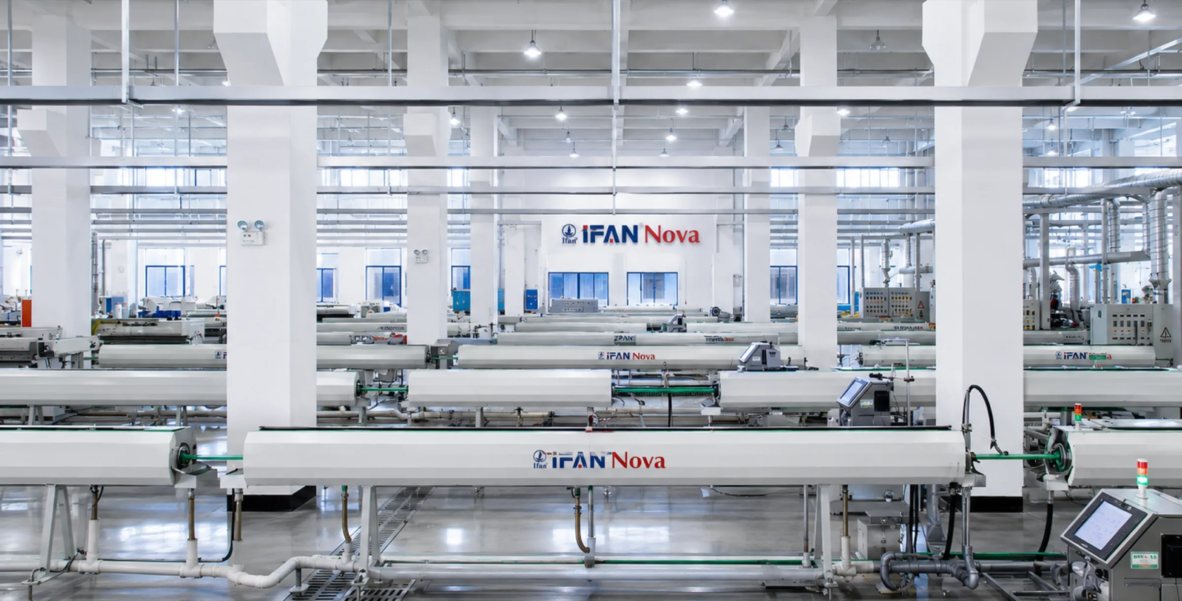
IFANNova is a French brand. Manufacturing is in our own facility, Zhuji Fengfan Piping Co., Ltd, Zhejiang: 30+ years, 1000+ employees, 118+ export countries, 120,000 m² (per our catalogue). Certifications on record: SKZ, CE, WRAS, DVGW, SGS, ISO 9001, ISO 14001 — certificate numbers: Coming soon. MOQ, lead time and pricing: Coming soon.
An enquiry that says “chilled water pipe, 500 m” cannot be answered. One that identifies the loop can be answered same-day. Tell us:
For material selection, sizing constraints, insulation and certification detail, return to the chilled water piping guide.
Expansion loops, anchors and guides for plastic chilled water pipe: how to size the offset leg, where to fix, and the engineering cost of choosing plastic.
Why the vapour barrier — not insulation thickness — decides whether chilled water insulation survives.
The chilled water failure mode that is not a leak: how ceiling-void condensation forms, how to tell it from a leak, and what actually prevents it.
