Chilled Water & HVAC · guide
Chilled water insulation thickness: ASHRAE 90.1 energy minimums vs BS 5422 condensation tables, and how to check any table against your own dew point.
A contractor insulates a chilled-water branch exactly to the specification’s thickness table, and six months later the ceiling tiles under it are stained. For fluid at 4 to 16 °C, Table 6.8.3-2 asks for 13 mm below 40 mm nominal size and 25 mm from 40 mm upward, for insulation of 0.030 to 0.039 W/(m·K) at a 24 °C mean. That is an energy minimum. Whether it also stops condensation depends on a number the table never prints: the dew point of the air around your pipe.
Our calculation for a 60.3 mm line at 5 °C in 25 °C air: 13 mm at 70 % RH, 21 mm at 80 %, 28 mm at 85 % and 42 mm at 90 %. Below: finding the dew point a table was built on, checking against your own with ISO 12241, and picking the row for plastic pipe.
Key takeaways
From 0:38, MEP Academy shows how dry bulb and relative humidity set the dew point, the number every thickness below is checked against.
Every thickness table answers one of two questions. An energy table limits heat gain per metre of pipe. A condensation table keeps the jacket warmer than the dew point of the air. A specification that quotes one without naming it leaves the contractor to guess.
The footnote to Table 6.8.3-2 reads: “These thicknesses are based on energy efficiency considerations only. Issues such as water vapor permeability or surface condensation sometimes require vapor retarders or additional insulation.” ASHRAE 90.1-2025 is the current edition and covers buildings except low-rise residential; we read the table as published in Addendum aq (2022), so check the edition your jurisdiction has adopted.
BS 5422:2023 prints both kinds. The BS 5422:2023 heat-gain table for the same high-emissivity product at 5 °C (Table 11) asks for 25 mm up to 21.3 mm OD, 30 mm from 26.9 up to 48.3 mm OD and 40 mm from 60.3 up to 114.3 mm, thicker than its condensation table. At 90 % RH our calculation for the same line (42 mm) overtakes it.
| Table | Question it answers | Design basis | DN 50 line at 5 °C (mm) | Best for |
|---|---|---|---|---|
| ASHRAE 90.1 Table 6.8.3-2 | Energy: heat gain | 4 to 16 °C fluid; 0.030 to 0.039 W/(m·K) | 25 | Energy-code compliance where 90.1 is adopted |
| BS 5422:2023 Table 11 (PAROC, emissivity ~0.9) | Energy: heat gain | Still air at 25 °C | 40 | UK energy specification for that product |
| BS 5422:2023 Table 6 (PAROC, emissivity ~0.9) | Condensation | 25 °C, 80 % RH, dew point 21.3 °C | 20 | Spaces that never exceed that dew point |
| BS 5422:2023 Table 8 (PAROC, emissivity ~0.05) | Condensation, bright foil finish | 25 °C, 80 % RH | 40 | Foil-faced or bright metal jackets |
| Our ISO 12241 calculation (0.040 W/(m·K)) | Condensation at your dew point | 25 °C, 85 % RH, dew point 22.3 °C | 28 (estimate) | Voids and plant rooms that can pass 80 % RH |
Source: ASHRAE Addendum aq to 90.1-2019 (2022), Table 6.8.3-2; BS 5422:2023 Tables 6, 8 and 11 as reproduced by PAROC for its stone wool sections; last row is our own calculation, explained below. DN 50 steel is 60.3 mm OD (ASME B36.10M). Compiled 28 September 2026.
For engineers and buyers pricing the branch pipework under these tables, our chilled-water piping range lists the sizes and pressure ratings we supply. The insulation specification stays with your designer.
Every condensation table carries a design dew point. The BS 5422:2023 condensation tables are built for still air at 25 °C and 80 % RH, a dew point of 21.3 °C, and calculated to BS EN ISO 12241:2022. The notes to those tables state the limit plainly: “In situations where the ambient air temperature is greater than 25 °C and/or the relative humidity exceeds 80%, these thicknesses will not be sufficient to control condensation.”
Chilled water normally runs at 4.4 to 7.2 °C, well below every dew point calculated on this page. The Magnus formula gives the dew point from dry-bulb temperature and RH: Dp = 243.12·H / (17.62 − H), where H = (log10(RH) − 2)/0.4343 + 17.62·T/(243.12 + T). At 25 °C the dew point is 19.1 °C at 70 % RH, 21.3 °C at 80 %, 22.3 °C at 85 % and 23.2 °C at 90 %. The 80 % result matches BS 5422’s figure, a quick check on your spreadsheet.
NIA, for indoor work: “Designing for an ambient relative humidity of 85% or higher is completely reasonable since it is necessary to prevent surface condensation 100% of the time indoors.” For outdoor lines and mechanical rooms vented to outside, NIA suggests designing for 90 % RH. If the pipe runs in a ceiling void, measure the void, not the office below it (see condensation damage in ceiling voids).
ISO 12241:2022 (published June 2022, replacing the 2008 edition) gives the calculation rules for building equipment and industrial installations. ISO 12241:2022 treats the insulation as a hollow cylinder with linear resistance ln(De/Di)/(2πλ) and the outer surface through a surface coefficient hse. The check takes four steps:
Inputs: fluid at 5 °C, air at 25 °C, elastomeric insulation at 0.28 Btu·in/h·ft²·°F (0.040 W/(m·K)), the ASTM C534 figure NAIMA lists, and a still-air surface. We used NIA’s surface conductance of 1.2 Btu/h·ft²·°F, 6.81 W/(m²·K). Two simplifications push the answer thicker: the pipe wall is ignored, and the conductivity is quoted at a 24 °C (75 °F) mean, higher than insulation shows at chilled-water temperatures. A plastic pipe wall adds resistance and helps you.
| RH at 25 °C (%) | Dew point (°C) | 32 mm OD (mm) | 60.3 mm OD (mm) | 110 mm OD (mm) |
|---|---|---|---|---|
| 70 | 19.1 | 12 | 13 | 13 |
| 80 | 21.3 | 19 | 21 | 23 |
| 85 | 22.3 | 25 | 28 | 31 |
| 90 | 23.2 | 37 | 42 | 47 |
Source: IFANNova calculation, 28 September 2026; minimum thickness for jacket at or above dew point, rounded up. Method: ISO 12241:2022 Formulae (6), (7) and (18). Inputs: NIA surface conductance, NAIMA CI226 conductivity, Sensirion Magnus constants. An estimate, not a specification.
With 25 mm the jacket sits at about 22.0 °C: above the 21.3 °C dew point at 80 % RH, below the 22.3 °C dew point at 85 %. One kelvin of dew point separates a dry ceiling from a wet one. From 85 % to 90 % the thickness rises by half again, from 28 mm to 42 mm.
| Relative humidity of the air at 25 °C (%) | Our ISO 12241 estimate, 60.3 mm OD (mm) | ASHRAE 90.1 energy minimum, 40 to <100 mm nominal (mm) | BS 5422:2023 Table 6, built for 80 % RH (mm) |
|---|---|---|---|
| 70 | 13 | 25 | — |
| 80 | 21 | 25 | 20 |
| 85 | 28 | 25 | — |
| 90 | 42 | 25 | — |
ISO 12241 itself warns that avoidance of dew formation cannot be reliably assured from minimal measurements and the basic calculation, and that local humidity variability matters.
The outer finish is the next lever. A shiny surface exchanges less radiant heat with the room, so on a cold line it needs more insulation to reach the same surface temperature. Bright aluminium has an emissivity of about 0.05; paint, rubber and cloth about 0.90.
BS 5422:2023 Table 6 (PAROC stone wool, high-emissivity finish, 5 °C content): 20 mm up to 88.9 mm OD, 25 mm at 114.3 mm. With a bright low-emissivity finish (Table 8) the same lines need 25 mm up to 17.2 mm OD, 30 mm from 21.3 up to 33.7 mm, 40 mm from 42.4 up to 88.9 mm and 50 mm at 114.3 mm. On a DN 50 steel line (60.3 mm OD), foil doubles the thickness. In NIA’s refrigeration-line example, painted aluminium jacketing cut the required thickness by almost 50 % against plain aluminium.
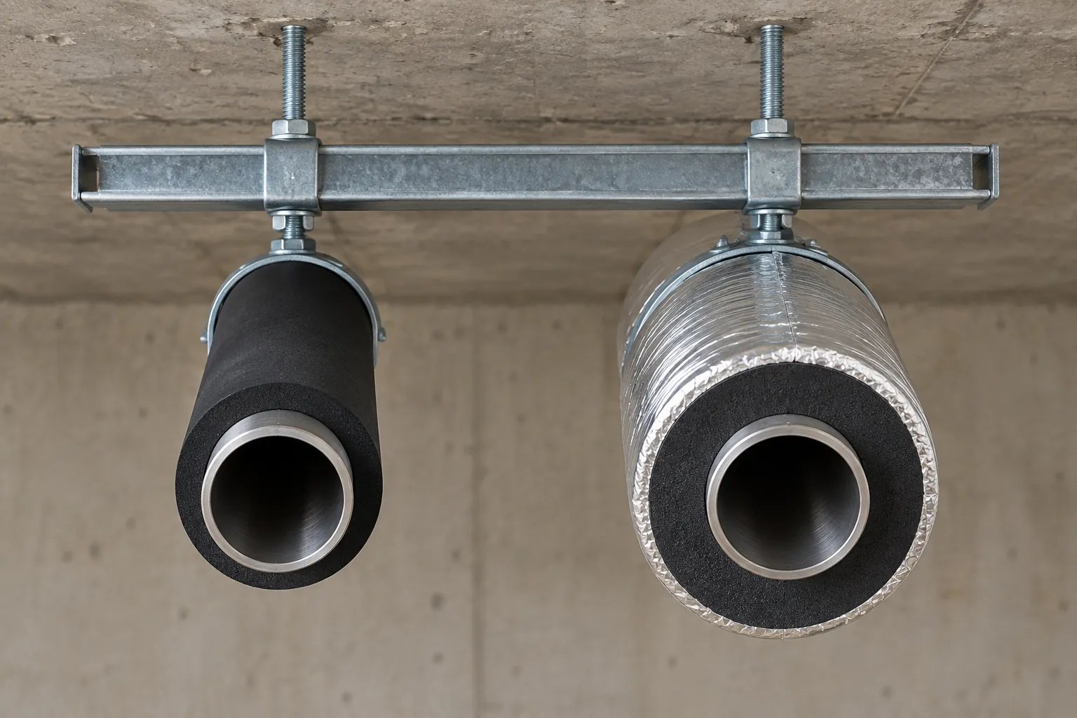
Outdoors the simple calculation weakens further. ISO 12241 notes that “except inside buildings, the average temperature of the radiant background seldom corresponds to the air temperature”, so for an outdoor line the calculated surface temperature is less reliable than indoors. Once vapour gets into the insulation, every number here is optimistic; the vapour barrier guide covers how that happens.
The ASHRAE table is based on steel pipe; nonmetallic pipe of Schedule 80 wall or thinner uses the same values, and a thinner layer on a heavier plastic wall needs documentation that heat transfer is no higher than on insulated steel. Condensation has no exemption either: the criterion is jacket temperature, whatever the pipe material.
Row selection trips up metric plastic pipe. BS 5422 rows are keyed to the outside diameter the insulation was based on (33.7, 42.4, 48.3, 60.3, 76.1, 88.9, 114.3 mm and so on). BS 5422:2023 replaced the 2009 edition and lists pipe sizes on a less-than-or-equal-to basis. So a 32 mm pipe reads from the 33.7 mm row and a 110 mm pipe from the 114.3 mm row.
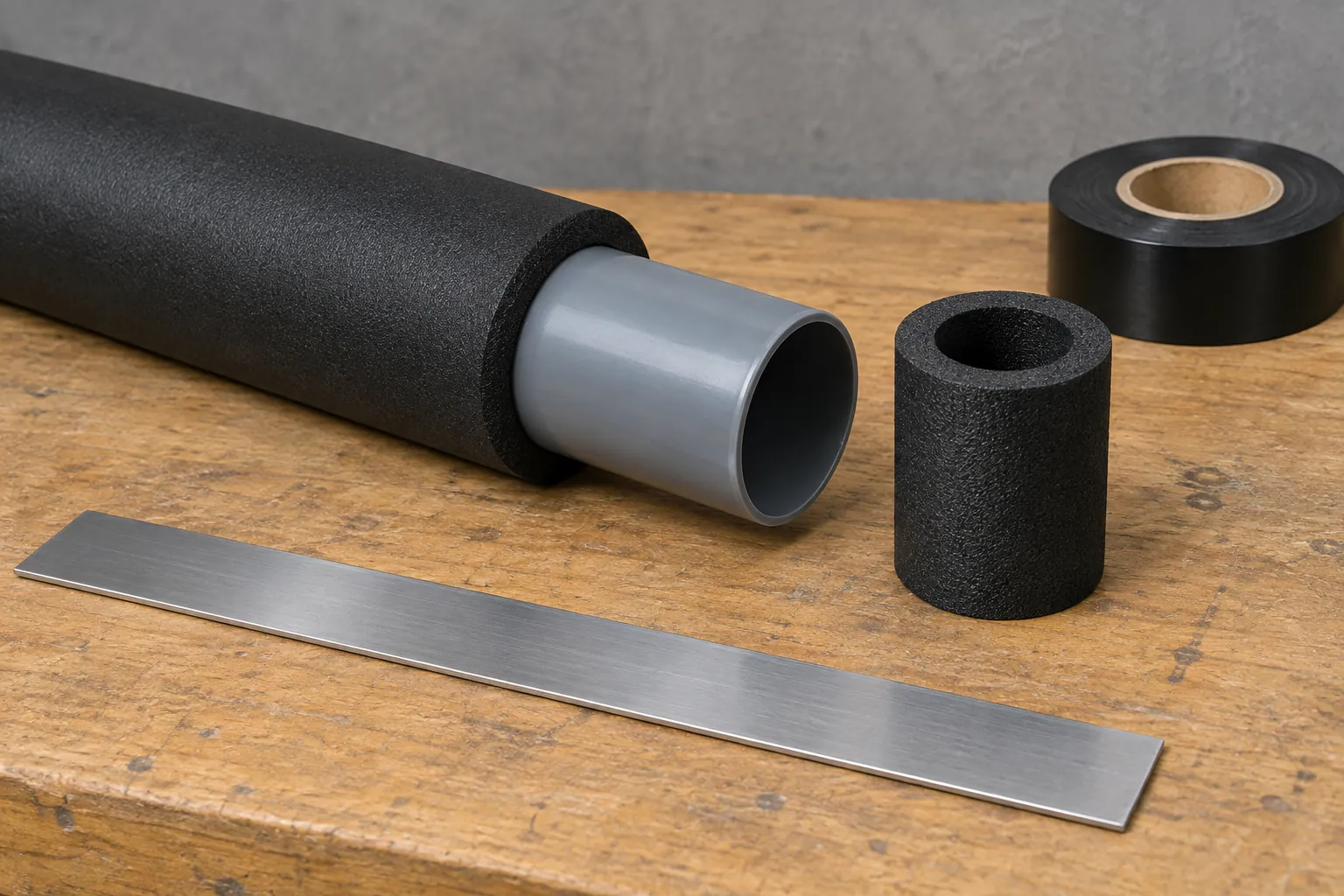
We supply PP-R PN20 in 20, 25 and 32 mm OD (see PP-R pipe and fittings), and UPVC 806 and HDPE from 20 to 110 mm OD; our pressure pipe stops at 110 mm (UPVC/CPVC 806). IFANNova is a French-designed, European-standard piping brand. We publish no insulation data and hold no lead-time figure. The variable that decides it: thickness tables are keyed to pipe OD, so send your insulation supplier the OD and thickness for each line and ask whether that pairing is a stock item or made to order. Ask us for the pipe’s plant-departure date on the same list.
Before accepting a thickness, run four checks:
For energy, ASHRAE 90.1 asks for 13 mm below 40 mm nominal size and 25 mm from 40 mm upward at 4 to 16 °C. For condensation it depends on dew point: our estimate for a 60.3 mm line at 5 °C is 21 mm at 80 % RH and 28 mm at 85 %.
Not necessarily. Its own footnote says the thicknesses are based on energy efficiency considerations only, and that surface condensation sometimes requires additional insulation. Check the jacket temperature against your dew point.
Measure dry-bulb temperature and RH, then apply the Magnus formula. At 25 °C the dew point is 19.1 °C at 70 % RH, 21.3 °C at 80 %, 22.3 °C at 85 % and 23.2 °C at 90 %.
Yes. ASHRAE 90.1 applies its table to nonmetallic pipe of Schedule 80 wall or thinner, and condensation depends on the jacket temperature, not the pipe material. A plastic wall adds some resistance but does not remove the need.