Our PPR line is three sizes deep. This page gives all three exactly, and explains why calling one of them “one inch” can put the wrong pipe on your site.
Most “PPR pipe sizes in mm and inches” tables you will find run to fourteen rows, from 12 mm to 160 mm, because that is what ISO 15874-2:2013 Table 5 tabulates for dimension class A. Our PPR line is not fourteen rows. It is three: 20 × 2.8 mm, 25 × 3.5 mm and 32 × 4.4 mm, all in 4 m lengths, all PN20 (per our catalogue). Above 32 mm: Coming soon.
That is not a limitation we intend to bury three screens down. It is the organising fact of this page. If you only have three sizes to sell, the useful thing to publish is not a fourteen-row chart copied off a standard — it is everything that is actually true about those three: the exact wall, the resulting bore, the inch name each one gets called in the trade, and the specific way that inch name goes wrong on a purchase order.
This page is deliberately narrow. It does not re-explain the four designation systems, the SDR-to-pressure formula, PN semantics, temperature derating or schedule numbers — all of that sits on the master pipe sizing charts page, with the clauses quoted. Come here for the three sizes. Go there for the systems.
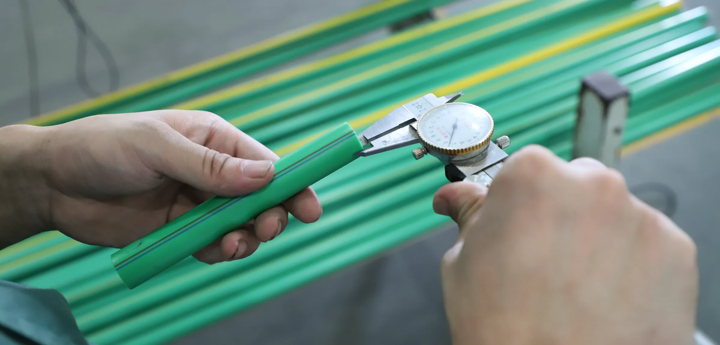
Here is the table. Everything in the first three columns is from our catalogue. The bore column is arithmetic on those two catalogue figures and is labelled as such, because outside diameter minus twice the wall is a subtraction anyone can check, not a manufacturing measurement.
| Designation (per our catalogue) | Outside diameter dn (mm) | Wall (mm) | Calculated bore (mm) | Bore area (mm²) | Length | Class |
|---|---|---|---|---|---|---|
| PPR 20 × 2.8 | 20 | 2.8 | 14.4 | 163 | 4 m | PN20 |
| PPR 25 × 3.5 | 25 | 3.5 | 18.0 | 254 | 4 m | PN20 |
| PPR 32 × 4.4 | 32 | 4.4 | 23.2 | 423 | 4 m | PN20 |
| Above 32 mm | Coming soon — not manufactured on this line, and not extrapolated from a formula | |||||
Sizes, walls, lengths and class per our catalogue. Bore = dn − 2 × wall; area = π(bore/2)², both plain arithmetic on the catalogue figures, rounded to the nearest whole mm² — not a measured or certified internal diameter, and not a flow rating.
Two things in that table are worth pausing on, because they are the numbers people get wrong when they specify PPR from a generic chart.
The wall is a large fraction of the pipe. On the 20 mm size, 2.8 mm of wall on each side consumes 5.6 mm of a 20 mm outside diameter. You are left with 14.4 mm of waterway inside a pipe everyone on site calls “20 mil”. Thick-walled PPR is not like steel or copper of the same nominal number, where the wall is a thin skin. Anyone sizing a branch by assuming the bore is close to the OD will oversize the flow and undersize the pipe.
Bore area does not scale the way the size labels suggest. Going from 20 to 25 is a 25% step in the label but a 56% step in bore area (163 → 254 mm², arithmetic on catalogue figures). Going 25 to 32 is a 28% step in label and a 67% step in area. In a three-size range, that is actually good news: the steps are coarse enough that you rarely need an intermediate size to hit a target, and where you do, the answer is to go up rather than to look for a 28 mm that does not exist in this series.
Cross-read our three catalogue walls against the wall thicknesses tabulated in ISO 15874-2:2013 Table 5 for dimension class A, and they land on a specific series.
| dn (mm) | Our wall (per our catalogue) | ISO 15874-2:2013 Table 5, S 5 | Table 5, S 3.2 | Table 5, S 2.5 | Table 5, S 2 |
|---|---|---|---|---|---|
| 20 | 2.8 | 1.9 | 2.8 | 3.4 | 4.1 |
| 25 | 3.5 | 2.3 | 3.5 | 4.2 | 5.1 |
| 32 | 4.4 | 2.9 | 4.4 | 5.4 | 6.5 |
Our walls per our catalogue; all other wall values from ISO 15874-2:2013 (Second edition, 2013-02-15) Table 5, dimension class A, in millimetres. Note that ISO 15874-2:2013 Table 5 footnote a restricts S 8, S 6.3 and S 4 to PP-RCT, so for plain PP-R in class A only S 5, S 3.2, S 2.5 and S 2 apply — those are the four columns shown.
All three of our walls coincide exactly with the S 3.2 column. That is a useful thing for a specifier to know, and it is the kind of statement we can make because it is a comparison of two published numbers, not an inference about performance.
Now the part that matters and that almost every PPR page online gets wrong. ISO 15874-2:2013 does not assign PN pressure classes to PP-R pipes. The familiar shorthand — “S 3.2 is PN16, S 2.5 is PN20” — is not in the standard. Nowhere in ISO 15874-2:2013 is a PN number attached to an S series. The marking requirement in Table 12 asks for “Application class combined with operating pressure — e.g. Class 1/10 bar”, not a PN figure, and it also requires the pipe dimension class to be marked, e.g. “A”.
The manufacturer Wavin Ekoplastik states the same thing independently: standards for hot and cold water installations “do not use the PN designation. S series are defined for pipes”, and for PP-RCT “The pipes of this material cannot be designated with PN; since the PN values are no longer specified in the standard.” Wavin adds the commercial reason the old labels persist: “Both values are used typically by the manufacturers considering the classic division using PN continues to be kept in mind by the customers” (Wavin Ekoplastik, Labeling of plastic pipes).
So what does PN20 on our catalogue mean? It means our catalogue designates this line PN20 (per our catalogue), which is the legacy commercial designation the market asks for. It is not a claim traceable to a clause of ISO 15874-2:2013, because that standard does not issue PN numbers for PP-R. If your specification requires a rating expressed in the form the standard actually uses — application class plus operating pressure — ask us for it against the specific project and we will answer against document rather than against a marketing label. The per-class allowable pressure figures: Coming soon. We have verified the standard’s method (Clause 6.2.2 selects a wall so the S series is at or below Scalc,max, derived per Annex A.3), but we did not extract the Annex A tables that carry the numbers, and we are not going to publish a bar figure from memory.
One more reason a single S series cannot map to a single PN for PP-R: the design stress changes with the application class. ISO 15874-2:2013 Annex A Table A.2 gives design stress σD for PP-R as 3.02 MPa in Class 1, 2.12 MPa in Class 2, 3.29 MPa in Class 4, 1.89 MPa in Class 5, and 6.93 MPa at 20 °C / 50 years. Since S is the quotient of design stress and allowable pressure (ISO 4065:2018, clause 4.2, equation 5: S = σs/PN), the same geometry yields a different allowable pressure in every application class. That is precisely why the standard rates by class instead of stamping one PN on the pipe.
This is the section this page exists for. Search demand for PPR sizing is heavily inch-shaped, and the honest answer is more useful than the chart people expect.
Start with arithmetic, because it settles the question quickly. A genuine unit conversion gives 1/2 inch = 12.7 mm and 3/4 inch = 19.05 mm. Neither figure is a nominal outside diameter anywhere in ISO 15874-2:2013 Table 5, whose class A series runs 12, 16, 20, 25, 32, 40, 50, 63, 75, 90, 110, 125, 140, 160 mm. There is no 12.7 and no 19.05. The mismatch is structural, not a rounding artefact.
Then look at what the inch designation actually measures. ISO 7-1:1994 Table 1 gives the major diameter — the thread outside diameter — for taper pipe threads: size 1/2 is 20.955 mm at 14 threads per inch; size 3/4 is 26.441 mm at 14 TPI; size 1 is 33.249 mm at 11 TPI; size 3/8 is 16.662 mm at 19 TPI; size 1/4 is 13.157 mm at 19 TPI. So a “1/2 inch” thread measures about 20.96 mm across the thread. The inch figure was never an outside diameter of anything.
Where did it come from? From the bore of the iron pipe the thread was designed to fit. As one thread reference puts it, “BSP nominal sizes originate from the bore diameter of the pipe the thread was designed to fit, not from the thread dimensions… A half-inch BSP nominal size refers to a pipe with approximately a half-inch internal bore, but the thread on the outside of that pipe measures around 20.9 mm” (The Hosemaster, BSP Thread Size & Identification Guide) — consistent with the 20.955 mm measured in ISO 7-1:1994.
Now put the three columns side by side.
| Our PPR size | Actual OD (mm, per our catalogue) | OD converted arithmetically (in) | Trade inch name commonly used | ISO 7-1:1994 thread major dia. for that inch size (mm) | True unit conversion of that inch label (mm) |
|---|---|---|---|---|---|
| 20 × 2.8 | 20 | 0.787 | “1/2 inch” | 20.955 | 12.70 |
| 25 × 3.5 | 25 | 0.984 | “3/4 inch” | 26.441 | 19.05 |
| 32 × 4.4 | 32 | 1.260 | “1 inch” | 33.249 | 25.40 |
Our sizes per our catalogue; the arithmetic inch column is the stated OD divided by 25.4, not a designation; thread major diameters from ISO 7-1:1994 (Third edition, 1994-05-15) Table 2; the last column is the literal unit conversion of the inch label. The trade name column is a market convention we observe and label as such — it is not a standards-defined equivalence.
Read the last three columns across and the whole confusion resolves. Take the 25 mm row. It gets called “3/4 inch”. A literal conversion of 3/4 inch is 19.05 mm, which is not the pipe. The ISO 7-1 thread called 3/4 measures 26.441 mm, which is also not the pipe. And the pipe’s own OD, 25 mm, converts arithmetically to 0.984 in — which is closer to one inch than to three quarters. Three different numbers, one label, none of them equal to each other.
We looked for an authoritative table pairing PP-R metric outside diameters with imperial thread sizes, published by a standards body or a trade association. We could not establish that one exists, and we think the absence is itself the answer.
The reasoning is straightforward once you read the two standards against each other. ISO 15874-2:2013 specifies PP-R pipe dimensions purely in metric nominal outside diameters, dn in millimetres, across Tables 5 to 8 — and never references an inch designation anywhere in those tables. ISO 7-1:1994 specifies thread sizes by inch designation, traceable to legacy iron-pipe bore, and never to a plastic pipe outside diameter. There is no bridging clause because the two documents are describing different objects.
What actually creates the pairing is a fitting. A manufacturer builds a threaded transition fitting with a socket on one end sized for a given PP-R OD and a thread on the other end of a given ISO 7-1 size, and by doing so establishes — commercially, in a catalogue — that this pipe goes with that thread. That is a product decision, and it can and does vary between manufacturers and product lines.
The practical consequence for a buyer is precise: any “20 mm = 1/2 inch” table you see should be read as a fitting-selection convention, and it is only authoritative for the specific manufacturer’s catalogue it came from. If you need a defensible cross-reference for a project, source it to a named fitting catalogue with a page reference, not to ISO or EN. Nobody at ISO wrote that row.
Our own threaded transition fittings sit in the 1138 series — 75 items in total (per our catalogue) — and our brass 2405 range is designated in inches from 1/4 in to 1 in (per our catalogue) precisely because it is thread-designated rather than diameter-designated. Item-by-item thread sizes and per-fitting dimensional data for those ranges: Coming soon. We will send the fitting pages against a specific enquiry rather than publish a pairing table we would then have to defend as a standard.
Of the three trade names, “1 inch PPR” is the one that causes real trouble, and it is worth walking through exactly how.
The phrase has at least three plausible readings, and they resolve to different pipes:
Reading A and Reading B differ by one full size step. In bore area that is 423 mm² against 254 mm² — a 66% difference in waterway (arithmetic on our catalogue figures). This is not a cosmetic discrepancy. A branch designed on the assumption of a 32 mm pipe and delivered as 25 mm has substantially less capacity, and the error will not be visible in a packing list that says “1 inch PPR, 400 m”.
It also does not self-correct on site, because both readings are physically buildable. 25 mm PPR fuses happily into 25 mm sockets and the system will hold pressure. It will simply be a smaller system than the one on the drawing. Undersizing that passes a pressure test is the expensive kind of undersizing.
The fix costs nothing. Write the metric OD and the wall on the line item, and put the inch name in brackets if you want it there for the site team. “PPR 32 × 4.4 mm, PN20, 4 m lengths (site name: 1 inch)” cannot be misread by anyone. “1 inch PPR” can be misread by everyone, including us.
One further note on our own range, and it points the other way. Our PPR stops at 32 mm (per our catalogue). If a specification calls for “1 1/4 inch” or “1 1/2 inch” PPR — whatever metric size the writer meant by those — that is above our line, and the answer is Coming soon, not a substitution. We will say so at enquiry stage rather than at delivery.
Here is a detail that catches out buyers working across Europe and that no generic “PPR sizes” chart mentions: ISO 15874-2:2013 does not have one universal size table. It has four.
Clause 6.2.1 states: “For the applicable pipe dimension class, the mean outside diameter, dem, of a pipe shall conform to Table 5, 6, 7 or 8, as applicable.” Table 5 is dimension class A, with sizes per ISO 4065:1996. Table 6 is class B1, described in the standard as “sizes based on copper pipe sizes for all classes of service conditions”. Tables 7 and 8 cover classes B2 and C. And Table 12 requires the dimension class to appear in the pipe marking, e.g. “A”.
Class B1 is the one to know about, because its sizes look nothing like the familiar series. It covers dn 10, 12, 15, 18, 22, 28 and 35 mm — copper-derived sizes. Wall thicknesses in that table, for example, are dn 22 at S 5 = 2.0, S 3.2 = 3.0, S 2.5 = 3.7, S 2 = 4.4 mm; and dn 28 at S 5 = 2.5, S 3.2 = 3.8, S 2.5 = 4.7, S 2 = 5.6 mm (ISO 15874-2:2013, Table 6). The same footnote applies: S 8, S 6.3 and S 4 are valid only for PP-RCT.
| Dimension class | ISO 15874-2:2013 table | Basis of the size series | Sizes near our range | Do we make it? |
|---|---|---|---|---|
| A | Table 5 | Sizes per ISO 4065:1996 | 12, 16, 20, 25, 32, 40, 50, 63, 75, 90, 110, 125, 140, 160 mm | 20, 25, 32 mm only (per our catalogue). Rest: Coming soon |
| B1 | Table 6 | Based on copper pipe sizes | 10, 12, 15, 18, 22, 28, 35 mm | Coming soon — not a series we list |
| B2 | Table 7 | Separate dimension class per Clause 6.2.1 | Table contents not extracted in our source review | Coming soon |
| C | Table 8 | Separate dimension class per Clause 6.2.1 | Table contents not extracted in our source review | Coming soon |
Class A and B1 sizes and walls from ISO 15874-2:2013 Tables 5 and 6; class structure and marking requirement from Clause 6.2.1 and Table 12; our range per our catalogue. We confirmed Tables 7 and 8 exist and are referenced by Clause 6.2, but we did not extract their numeric contents, so we are not listing sizes for classes B2 and C.
Why this matters commercially: a UK or Irish specification written around 15 mm and 22 mm PPR is a class B1 specification. Our 20 mm and 25 mm are class A. Twenty is not fifteen and twenty-five is not twenty-two — they are adjacent numbers from two different series, and the fittings are not interchangeable. If a bill of quantities is in 15/22/28, do not quietly read it as 20/25/32. Ask which class is marked on the pipe the specifier had in mind, because ISO 15874-2:2013 Table 12 requires that marking to be there.
Our three walls sit on S 3.2 as shown in section 2. If you want to check that against any other PP-R offer, here is the arithmetic the standards themselves provide — restricted to what is needed for these three sizes. The general treatment of SDR and the pressure formula lives on the sizing charts page; this is just the PP-R-specific piece.
ISO 4065:2018 clause 3.6 defines pipe series S as a “dimensionless number related to the nominal outside diameter dn and nominal wall thickness en given by the following formula: S = (SDR − 1) / 2″. Rearranged, SDR = 2S + 1. Applying that to the S values tabulated in ISO 15874-2:2013 Table 5 gives the pairs relevant to PP-R:
| Pipe series S (ISO 15874-2 Table 5) | SDR from SDR = 2S + 1 | Calculated S value (ISO 4065:2018 Table 2) | Valid for plain PP-R in class A? |
|---|---|---|---|
| S 2 | 5 | 1.9953 | Yes |
| S 2.5 | 6 | 2.5119 | Yes |
| S 3.2 | 7.4 | 3.1623 | Yes — this is where our three walls sit |
| S 4 | 9 | 3.9811 | No — PP-RCT only (Table 5 footnote a) |
| S 5 | 11 | 5.0119 | Yes |
| S 6.3 | 13.6 | 6.3096 | No — PP-RCT only (Table 5 footnote a) |
| S 8 | 17 | 7.9433 | No — PP-RCT only (Table 5 footnote a) |
S values and the PP-RCT restriction from ISO 15874-2:2013 Table 5 and its footnote a; the SDR column is ISO 4065:2018 clause 3.6’s own formula applied to those S values; calculated S values from ISO 4065:2018 Table 2; the “valid for plain PP-R” column is our reading of footnote a. The comparison to our walls is against our catalogue figures.
Two features of that table are worth naming, because both trip people up.
SDR 7.4 is not a round number, and that is by design. ISO 4065:2018 clause 3.5 defines SDR as a “numerical designation of a pipe series, which is a convenient round number, approximately equal to the ratio of the nominal outside diameter dn of a pipe to its nominal wall thickness en“. The word “approximately” is in the standard’s own text. And ISO 4065:2018 Table 2 shows why: the nominal S labels are rounded versions of calculated values (S 3.2 is really 3.1623), drawn from the R 10 series of preferred numbers in ISO 3, with S 11.2 and S 14 coming from the R 20 series. SDR is a label, not a computed quotient — so do not expect dn ÷ wall to land exactly on it.
You can verify that on our own figures. 20 ÷ 2.8 = 7.14; 25 ÷ 3.5 = 7.14; 32 ÷ 4.4 = 7.27 (arithmetic on our catalogue figures). All three cluster near but not on SDR 7.4, exactly as the standard’s word “approximately” predicts.
Half the S series is off-limits for plain PP-R. Three of the seven series in Table 5 — S 8, S 6.3 and S 4 — carry footnote a, “Only valid for PP-RCT”. If you are comparing a competitor’s thin-wall PP-R offer at S 6.3, the material grade is part of the question, not a detail.
This one is genuinely useful and almost never mentioned in size charts, because it only bites at the small end — which is where our whole range lives.
ISO 15874-2:2013 Clause 6.2.2 states: “However, pipes intended to be joined together by fusion shall have a minimum wall thickness of 2,0 mm.” That is an absolute floor, independent of what the geometry calculation gives.
The reason is physical rather than hydraulic. A socket fusion joint needs enough material in the wall to melt, flow and form a bead. Below roughly 2 mm there is not enough wall to make a reliable fused joint, whatever the pressure arithmetic says. So the standard imposes the floor.
The consequence for chart-reading: on thin series at small diameters, the tabulated wall is the 2.0 mm floor rather than the value the S formula would produce. ISO 4065:2018 clause 4.2 equation (3) gives en = [1 / (2S + 1)] × dn. Run that for dn 20 at S 5 and it returns 1.82 mm — below the fusion floor. ISO 15874-2:2013 Table 5 shows 1.9 mm at that cell, which is neither the pure formula result nor a coincidence: the small sizes in thin series are floor-governed, not formula-governed.
None of our three sizes is anywhere near that floor. At 2.8, 3.5 and 4.4 mm (per our catalogue) they clear the 2.0 mm minimum by 40% to 120%. That is not a performance claim on our part — it is simply where S 3.2 lands at these diameters — but it does mean the fusion floor is not a constraint you need to check on this range.
People searching for “PPR pipe sizes in mm and inches pdf” want one sheet they can print and take to a meeting. Here is that sheet, in the form we can actually stand behind. Everything is sourced in the row it sits on.
| IFANNova PPR quick reference — the complete manufactured range | |
|---|---|
| Product line | PPR pipe 1103 with 1138 fitting series, 75 items (per our catalogue) |
| Sizes manufactured | 20 × 2.8 mm; 25 × 3.5 mm; 32 × 4.4 mm (per our catalogue) — three sizes, complete list |
| Sizes above 32 mm | Coming soon — not manufactured, not extrapolated |
| Standard length | 4 m per length, all three sizes (per our catalogue) |
| Class marked | PN20 (per our catalogue). Note: ISO 15874-2:2013 does not assign PN classes to PP-R — see section 2 |
| Calculated bore | 14.4 / 18.0 / 23.2 mm (arithmetic: dn − 2 × wall, on catalogue figures) |
| Arithmetic inch OD | 0.787 / 0.984 / 1.260 in (OD ÷ 25.4 — not a designation) |
| Trade inch names in circulation | “1/2” / “3/4” / “1 inch” — market convention only, no standards basis (see sections 3 and 4) |
| ISO series the walls coincide with | S 3.2 in ISO 15874-2:2013 Table 5, dimension class A (cross-read of our catalogue walls against the standard’s table) |
| Corresponding SDR | 7.4, from SDR = 2S + 1 (ISO 4065:2018, clause 3.6) |
| Fusion minimum wall | 2.0 mm absolute (ISO 15874-2:2013, Clause 6.2.2) — all three sizes clear it comfortably |
| Governing standard for PP-R pipe dimensions | ISO 15874-2:2013 (Second edition, 2013-02-15), “Plastics piping systems for hot and cold water installations — Polypropylene (PP) — Part 2: Pipes” |
| Allowable pressure per application class | Coming soon — requires ISO 15874-2:2013 Annex A tables we did not extract; will not be published from memory |
| Certificates | SKZ, CE, WRAS, DVGW, SGS, ISO 9001, ISO 14001 (per our catalogue). Certificate numbers: Coming soon |
| MOQ, lead time, price | Coming soon — quoted per enquiry |
| Downloadable PDF of this table | Coming soon — in preparation; the table above is the complete data set it will contain |
Let us be explicit about what is not on that sheet, and why, because the omissions are the point.
There is no row-by-row wall thickness table for sizes we do not make. Our catalogue does not carry intermediate wall data, and we could not obtain the full text of ISO 4065:2018 Table 3 — the universal wall thickness table — from an accessible source. We could reconstruct walls from the formula en = [1 / (2S + 1)] × dn. We are not going to, because a formula output presented as product data is a fabrication with a decimal point on it.
There is no “20 mm = 1/2 inch” conversion row presented as a standard. Section 4 explains why: no such standards-defined conversion exists, and the pairing is a per-manufacturer fitting convention.
There is no pressure-at-temperature table. That needs ISO 15874-2:2013 Annex A Tables A.3–A.6, which we did not extract, and ISO 15874-1:2013 Table 1 for the application class definitions, which we did not open. Marked Coming soon rather than filled with a plausible number.
And there is no DIN 8077 comparison. DIN 8077, “Polypropylene (PP) pipes — PP-H, PP-B, PP-R, PP-RCT — Dimensions”, is the German national dimensional standard for PP pipes and runs alongside ISO 15874 (ANSI Webstore catalogue entry for DIN 8077:2008). We reached the catalogue entry with the title and scope, but not the table values, so we cannot state that DIN 8077’s dimensions are identical to ISO 15874-2:2013 Table 5. Many pages assert that they are. We have not verified it and will not repeat it. (Separately, and confusingly, our HDPE pipe — a different line entirely — is marked “GERMANY STANDARD DIN8077/8078” per our catalogue.)
You will be comparing our three sizes against other offers. These are the checks that separate a real specification from a copied chart, in the order that finds problems fastest. This section is our commercial experience and reading of the standards, not a standards requirement.
Three sizes at 20, 25 and 32 mm is a terminal-branch range. In our commercial experience that is where PPR does most of its work anyway: fixture connections, branch runs off a riser, equipment tails, small-diameter hot and cold distribution inside a unit. Our PPR is not a distribution main product and cannot be made into one by adding rows to a chart.
To be direct about the ceiling across our whole catalogue, since PPR is the tightest line in it: our pressure pipe production stops at Φ110 for UPVC 806 and HDPE, both PN16, and at 32 mm for PPR (per our catalogue). In PVC 902 only the 1902 fittings reach Φ160 — the pipe stops at Φ110 — and the line is non-pressure drainage only, so it must never be substituted into a pressure duty because the number is bigger. We do not supply DN 150–400 distribution mains in any material. If your bill of quantities is built around them, split the enquiry and send us the portion at or below our ceilings.
On origin, since it comes up on every first enquiry: IFANNova is a French brand. Manufacturing is by Zhuji Fengfan Piping Co., Ltd in Zhejiang, China (per our catalogue) — 30+ years, 1000+ employees, exports to 118+ countries, 10,000 sets of moulds, 120,000 m² of plant. Nothing in our range is made in France. We would rather state that on a public page than have it discovered during a factory audit.
What PPR pipe sizes do you actually make? Three: 20 × 2.8 mm, 25 × 3.5 mm and 32 × 4.4 mm, all 4 m lengths, all designated PN20 (per our catalogue). That is the complete list, not a selection from a longer one. Above 32 mm: Coming soon.
Is 20 mm PPR the same as 1/2 inch? No, and the question has no standards answer. 1/2 inch converts literally to 12.70 mm, which is not a PP-R nominal size in ISO 15874-2:2013 Table 5. The ISO 7-1:1994 thread called 1/2 has a major diameter of 20.955 mm. And 20 mm PPR converts arithmetically to 0.787 in. “1/2 inch” is a trade name for the 20 mm size, established by which threaded transition fittings manufacturers pair with it — a commercial convention, not a unit conversion.
What is the inside diameter of 25 mm PPR? Subtracting our catalogue wall from our catalogue OD gives 25 − (2 × 3.5) = 18.0 mm. That is arithmetic on published nominal figures, not a measured or certified bore, and it does not account for any tolerance band. ISO 15874-2:2013 Table 5 gives mean outside diameter tolerances of 25 to 25.3 mm at dn 25, so the real bore varies within a band.
Is your PPR SDR 11 or SDR 7.4? Our three walls coincide with the S 3.2 column of ISO 15874-2:2013 Table 5, dimension class A. Applying ISO 4065:2018 clause 3.6’s formula SDR = 2S + 1 gives SDR 7.4. Dividing our catalogue figures directly gives 7.14, 7.14 and 7.27 — near but not on 7.4, which is expected, since ISO 4065:2018 clause 3.5 describes SDR as “a convenient round number, approximately equal to the ratio”.
Why does your catalogue say PN20 if ISO 15874-2 does not use PN? Because the market asks for PN and has done for decades. Wavin Ekoplastik puts it plainly: “Both values are used typically by the manufacturers considering the classic division using PN continues to be kept in mind by the customers.” PN20 on our catalogue is a commercial designation (per our catalogue). The standard’s own rating scheme is application class plus operating pressure, per ISO 15874-2:2013 Table 12. If you need the rating in the standard’s form for a submittal, ask — the per-class figures are Coming soon on this page because we have not extracted the Annex A tables that carry them.
Do you make 15 mm or 22 mm PPR? No — Coming soon, and note those are class B1 sizes. ISO 15874-2:2013 Table 6 covers dimension class B1 at dn 10, 12, 15, 18, 22, 28 and 35 mm, described in the standard as “sizes based on copper pipe sizes”. Our 20/25/32 are class A. Do not read a 15/22 specification as 20/25.
Can you send a PDF of the PPR size chart? A printable version is in preparation; availability Coming soon. The table in section 9 is the complete data set it will contain — we are not holding back rows behind a download.
What pressure can 20 mm PPR take at 70 °C? We are not going to give you a number here. Deriving it properly requires ISO 15874-2:2013 Annex A Tables A.3–A.6 for the Scalc,max values and ISO 15874-1:2013 Table 1 for what each application class means in temperature and duration; we verified the method (Clause 6.2.2 and Annex A.3) but did not extract those tables. What we can point to is why one number cannot cover it: ISO 15874-2:2013 Annex A Table A.2 gives PP-R design stress as 3.02 MPa in Class 1, 2.12 in Class 2, 3.29 in Class 4, 1.89 in Class 5 and 6.93 at 20 °C / 50 years. Same pipe, five different design stresses. Send the application class and the duty and we will answer against document. Coming soon as a published table.
Are your PPR fittings compatible with other brands’ 20/25/32 mm PPR? Fusion jointing between brands is a question we will not answer generically. Our 1138 fitting series, 75 items, is matched to our own 1103 pipe (per our catalogue). Cross-brand compatibility data: Coming soon.
Where is it made? IFANNova is a French brand; manufacture is by Zhuji Fengfan Piping Co., Ltd in Zhejiang, China (per our catalogue). Nothing in our range is made in France.
MOQ, lead time and price? Coming soon — quoted per enquiry.
If your drawing says “1 inch PPR”, tell us and we will ask the one question that resolves it — 32 mm or 25 mm — before anything is quoted, let alone shipped. If it says a size above 32 mm, you will get a straight “outside our range” the same day rather than a hopeful quotation.
Our catalogue states a wall thickness for every diameter we make.
Read a PPR size wrong and it gets expensive fast — a fitting that won’t fuse, a hot line specced at the wrong pressure class, an on-site swap that stalls the job.
We got a standard number wrong, we are saying so on the page rather than deleting it, and the corrected guide is one click away.
