Chilled Water Pipe Size Chart: DN, Flow Rate and Velocity
Bore, not the dn number, decides flow: derived bore and derived flow for dn 20 to dn 110, with the velocity limits quoted source by source.
A dn 50 pipe in UPVC/CPVC 806 PN16 has a 42.6 mm bore, and at 1.2 m/s it carries 1.71 L/s. Bore decides flow. The number printed on plastics pipe is the outside diameter, so it overstates the bore by twice the wall thickness, and a chart keyed to steel nominal sizes overstates it again. Table 1 gives the derived bore and the derived flow for all nine catalogue sizes, dn 20 to dn 110, at the velocities the published guidance names. Bore is dn minus twice the catalogue wall. Flow is Q = V × A. Both are printed, so any row can be rechecked.
Every row of Table 1 is a branch like this. The chart stops at dn 110 because the range does.
Key Takeaways
Bore, not the dn number, sets capacity: dn 50 in UPVC/CPVC 806 PN16 has a derived 42.6 mm bore carrying 1.71 L/s at 1.2 m/s; dn 110 has 95.6 mm carrying 8.61 L/s.
ASHRAE Handbook—Fundamentals 2025, Chapter 22, section 3.1 reports “one recommendation” of a 1.2 m/s velocity limit for 50 mm pipe and smaller and a 400 Pa/m pressure-drop limit above 50 mm.
CIBSE Journal CPD Module 32 (September 2011) gives under 1 m/s for small domestic systems rising to 3 m/s at 50 mm and above, and calls these norms “certainly not hard absolute rules”.
ISO 161-1:2018 defines dn as the nominal outside diameter; ASME B36.10M-2004 calls DN a dimensionless designator and states the inside-diameter-equals-nominal-size relation no longer holds.
Read a DN 50 steel drawing as dn 50 plastics and the same flow runs at a derived 1.52 times the velocity; the bore that matches DN 50 is dn 63.
The chart stops at dn 110, which is where IFANNova pressure pipe stops; DN 150 to DN 400 mains are not made.
Practical Engineering on why a narrower bore spends pressure, not just velocity; the diameter segment opens at 5:15. Neutral educational video, not an IFANNova production.
Chilled Water Pipe Size Chart: Bore and Flow, dn 20 to dn 110
Read the chart by bore. Find the flow the branch has to carry, then take the first size whose 1.2 m/s column reaches it. One catalogue step is a large step: dn 63 at 2.71 L/s carries 58 percent more than dn 50 at 1.71 L/s, because flow area goes with the square of the bore.
Table 1. Chilled water pipe size chart, IFANNova UPVC/CPVC 806 PN16 (WP55 pipe, 4 m lengths). dn and wall thickness are catalogue values (grounding fact-1). Bore and both flow columns are derived: bore = dn − 2 × wall (fact-14), flow Q = V × A with A = πd²/4 (fact-15). The 3.0 m/s column is printed only where the derived bore passes 50 mm, because the 50 mm threshold in the cited guidance is a pipe diameter stated for steel (BSRIA BG 30/2007, Sheet W1); below it the cited figure is 1.2 m/s (ASHRAE Handbook—Fundamentals 2025, Chapter 22, section 3.1). Compiled 12 September 2026.
dn (mm)
Catalogue wall (mm)
Derived bore (mm)
Flow at 1.2 m/s (L/s, derived)
Flow at 3.0 m/s (L/s, derived)
20
2.0
16.0
0.24
—
25
2.0
21.0
0.42
—
32
2.4
27.2
0.70
—
40
3.0
34.0
1.09
—
50
3.7
42.6
1.71
—
63
4.7
53.6
2.71
6.77
75
5.6
63.8
3.84
9.59
90
6.7
76.6
5.53
13.83
110
7.2
95.6
8.61
21.53
Need the sizes in the first column, by the container?
For MEP contractors and importers specifying branch and riser sizes at container volume: the UPVC/CPVC 806 PN16 range charted above, dn 20 to dn 110, with the per-size wall thicknesses these bores were computed from.
Where the Velocity Limits Come From, Source by Source
Four sources, and they do not limit the same quantity. The ASHRAE Handbook—Fundamentals caps velocity at 50 mm and below, then switches to a pressure gradient. The CIBSE CPD module reaches 3 m/s only at 50 mm and above. Averaging them produces a band no source stands behind, so they sit side by side with their scopes.
Table 2. What each source actually limits, with its edition and year. Quoted, not averaged: ASHRAE caps velocity only at 50 mm and below and hands over to a pressure gradient above that, while the CIBSE module reaches 3 m/s only at 50 mm and above and calls its own figures traditional norms rather than rules. BSRIA BG 30/2007 writes its velocity limits for “steel pipe up to 50 mm diameter” and “steel pipe over 50 mm diameter”; its velocity figures are not reproduced here because the published PDF drops the decimal points and a reconstructed number is a guess (fact-10). Sources: fact-5 to fact-10. Read 12 September 2026.
Traditional norm for velocity, “not hard absolute rules”
Under 1 m/s small domestic; 3 m/s at 50 mm and above
1 to 3 m/s
CIBSE Journal CPD Module 32, September 2011
Typical design pressure drop
Commercial and domestic piped systems
about 300 Pa/m
BSRIA BG 30/2007, Sheet W1
Typical pressure-drop range; Guide C starting point 250 Pa/m
Re-circulating systems, sizes over 50 mm
100 to 300 Pa/m
The 50 mm in these rules is a pipe diameter written for steel. A 50 mm steel pipe has a derived 52.5 mm bore, which in this catalogue is dn 63. That is why the 3.0 m/s column starts there.
Flow rises with the square of the bore: dn 50 to dn 63 adds 58 percent of capacity at one velocity. The dashed marker is the 52.5 mm bore of a 50 mm steel pipe, where the cited guidance changes criterion; the 3.0 m/s series starts there. Method: bore = dn minus twice the catalogue wall (fact-14), flow Q = V x A (fact-15); 1.2 m/s is the figure ASHRAE Ch. 22 s. 3.1 reports as "one recommendation" (fact-5) and 3.0 m/s a CIBSE norm its own text calls "certainly not hard absolute rules" (fact-9).
Derived flow against derived bore, UPVC/CPVC 806 PN16, dn 20 to dn 110. Source and method: bore = dn minus twice the catalogue wall (fact-14), flow Q = V x A (fact-15); 1.2 m/s is the figure ASHRAE Ch. 22 s. 3.1 reports as "one recommendation" (fact-5) and 3.0 m/s a CIBSE norm its own text calls "certainly not hard absolute rules" (fact-9).
Derived bore (mm) — dn minus twice the catalogue wall
Flow at 1.2 m/s (L/s, derived)
Flow at 3.0 m/s (L/s, derived)
16.0
0.24
—
21.0
0.42
—
27.2
0.7
—
34.0
1.09
—
42.6
1.71
—
53.6
2.71
6.77
63.8
3.84
9.59
76.6
5.53
13.83
95.6
8.61
21.53
Why a DN 50 Bore Is Not a dn 50 Bore
Two lists, two meanings. ISO 161-1:2018 defines dn as the nominal outside diameter; its Table 1 runs 16, 20, 25, 32, 40, 50, 63, 75, 90, 110, 125, 140, 160 mm. There is no dn 80 or dn 100. Steel uses DN 15 to DN 100, and ASME B36.10M-2004 calls DN a dimensionless designator. It records why: the outside diameter was once chosen so the bore would approximate the nominal size, “Although there is no such relation” now.
Table 3. The same number read across two systems. Steel bores are derived from ASME B36.10M-2004 Table 1 outside diameters and STD / Schedule 40 walls (fact-13, fact-16); plastics bores are derived from the catalogue walls in Table 1 (fact-14). The velocity column is derived as (steel bore / plastics bore)², the factor by which velocity rises if the same flow is pushed through the smaller bore (fact-17). The last column is the catalogue size whose bore comes closest to the steel bore (fact-18); † marks a pairing where that size is still narrower than the steel bore. Across all nine DN 15 to DN 100 pairings, six meet or beat the steel bore and three fall short: DN 32 by 1.1 mm and 6 percent of flow area, DN 80 by 1.3 mm and 3 percent, DN 100 by 6.7 mm and 13 percent. DN 15, DN 65, DN 80 and DN 100 are the four steel sizes with no same-number dn counterpart in the ISO 161-1:2018 series, so they have no row here; their pairings are listed in fact-18. Compiled 12 September 2026.
Number on the drawing
Steel Sch 40 bore (mm)
Plastics 806 bore (mm)
Velocity at equal flow
Pick instead (dn, mm)
DN 20 vs dn 20
21.0
16.0
1.72×
dn 25 (21.0 mm)
DN 25 vs dn 25
26.6
21.0
1.60×
dn 32 (27.2 mm)
DN 32 vs dn 32
35.1
27.2
1.67×
dn 40 (34.0 mm) †
DN 40 vs dn 40
40.9
34.0
1.45×
dn 50 (42.6 mm)
DN 50 vs dn 50
52.5
42.6
1.52×
dn 63 (53.6 mm)
One step up the dn series meets or beats the steel bore in six of the nine pairings. Three fall short: DN 32, where dn 40’s 34.0 mm is 1.1 mm and 6 percent of flow area under the 35.1 mm steel bore; DN 80, where dn 90 is 1.3 mm and 3 percent under 77.9 mm; DN 100, where dn 110 is 6.7 mm and 13 percent under 102.3 mm.
Change the Material and the Chart Changes
Wall thickness sets the bore, so one dn gives three bores. At dn 50 that is 42.6 mm in UPVC/CPVC 806 against 40.8 mm in HDPE: 9 percent of flow area from 0.9 mm of wall. A chart printing one internal diameter per dn has picked a material without saying so.
Table 4. One dn, three wall series, three bores. Walls are catalogue values (fact-1, fact-2, fact-3); bores and the flow spread are derived (fact-14, fact-15). PPR 1103 PN20 is made in three sizes only, which is the real limit of that line and not a gap in the published data. HDPE appears here for wall thickness and derived bore: the pipe body is marked GERMANY STANDARD DIN8077/8078, those are PP standards, and the pressure class is awaiting internal confirmation, so no class is stated. Compiled 12 September 2026.
dn (mm)
UPVC/CPVC 806 bore (mm)
HDPE bore (mm)
PPR PN20 bore (mm)
Flow spread at 1.2 m/s (L/s, derived)
20
16.0
15.4
14.4
0.20 to 0.24
25
21.0
20.4
18.0
0.31 to 0.42
32
27.2
26.0
23.2
0.51 to 0.70
40
34.0
32.6
—
1.00 to 1.09
50
42.6
40.8
—
1.57 to 1.71
63
53.6
51.4
—
2.49 to 2.71
75
63.8
61.4
—
3.55 to 3.84
90
76.6
73.6
—
5.11 to 5.53
110
95.6
90.0
—
7.63 to 8.61
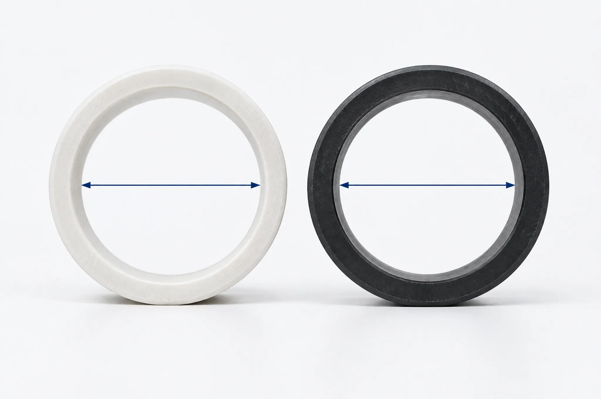
An illustration, not a photograph of production pipe. One outside diameter, two wall series: the thicker wall leaves the narrower bore, which is the whole 42.6 against 40.8 mm gap in Table 4. Walls drawn heavier than scale.
Re-Deriving a Row, and Where Our Range Stops
Two steps, worked on dn 63. Bore = 63 − (2 × 4.7) = 53.6 mm. Area = π × 0.0536² / 4 = 0.002256 m², so at 1.2 m/s the flow is 0.002707 m³/s, which is 2.71 L/s. Every row in this page is that calculation.
Three limits come with it:
The arithmetic is nominal. It ignores dimensional tolerance and the minimum-wall conventions used for PE and PP, so a delivered pipe runs marginally tighter than the table says.
Velocity is half the criterion. BSRIA BG 30/2007 puts the typical re-circulating range at 100 to 300 Pa/m, with a 250 Pa/m starting point; ASHRAE’s figure above 50 mm is 400 Pa/m. The pressure drop over your own run length and fittings is what finally fixes the size. The worked sizing example carries that calculation, and the designation and SDR tables carry the dimensional side.
The chart ends at dn 110, because the pressure-pipe range ends there. DN 150 to DN 400 mains are not made and are not subcontracted, and insulation thickness is a condensation question rather than a size question (see vapour barrier failures).
Take the chart in this order, and it will not mislead you:
Decide the flow each branch carries, in L/s.
Pick the velocity criterion you will defend, and name its source: 1.2 m/s below 50 mm from ASHRAE, or a figure from your project specification.
Read Table 1 by bore and take the first size that reaches the flow.
If the drawing is in steel DN, move one step up the dn series, then check the DN 32, DN 80 and DN 100 shortfalls above.
Check the pressure drop over the real run before the size is final, and confirm the wall series of the pipe you are actually quoting.
Frequently Asked Questions
What kind of pipe is used for chilled water?
Plant piping and the larger mains are normally steel or copper. Branches and the tails to fan-coil and air-handling units are where thermoplastics sit: PVC-U and CPVC, PE and PP-R. IFANNova makes that segment, dn 20 to dn 110 in UPVC/CPVC 806 PN16 and in HDPE, plus PPR PN20 at dn 20, 25 and 32.
What are the common sizes of cold water pipes in mm?
ISO 161-1:2018 Table 1 fixes the metric thermoplastics series: 16, 20, 25, 32, 40, 50, 63, 75, 90, 110, 125, 140 and 160 mm in the building range, all of them outside diameters. Steel uses DN 15, 20, 25, 32, 40, 50, 65, 80 and 100, where the number is a dimensionless designator, not a measurement (ASME B36.10M-2004).
What is the rule of thumb for chilled water pipe sizing?
No standards body owns one. ASHRAE Handbook—Fundamentals 2025, Chapter 22, section 3.1 reports “one recommendation” of 1.2 m/s for 50 mm pipe and smaller with 400 Pa/m above that, and quotes Carrier (1960) that velocity should not exceed 4.6 m/s in any case. CIBSE Journal CPD Module 32 calls its 1 to 3 m/s range “certainly not hard absolute rules”.
Is DN 50 the same as 50 mm pipe?
No. On plastics pipe dn 50 is the nominal outside diameter (ISO 161-1:2018), and a PN16 806 pipe at that size has a derived 42.6 mm bore. On steel, DN 50 designates a pipe of 60.3 mm outside diameter whose Schedule 40 bore is a derived 52.5 mm (ASME B36.10M-2004 Table 1). The matching plastics size is dn 63.
Written by the IFANNova Technical Team (Engineering & Export), from catalogue data and the published standards named above.
Reviewed 12 September 2026. Derived columns are marked derived and the equations are printed, so every row can be recomputed. Figures the team could not verify are left out rather than filled in.