Four designation systems that do not agree with each other, reconciled against the sizes we actually manufacture. Every value carries its source: the full per-size wall thickness tables for UPVC/CPVC 806, HDPE, PVC 902 and PPR are published in full below, and the two places our catalogue genuinely stops are named.
Most sizing errors on an imported piping package are not arithmetic errors. They happen because the buyer, the consultant and the factory are each using a different designation system, and all three print a number that looks like a diameter. DN 100 is not 100 mm. NPS 4 is not 4 in bore. SDR 11 is not a pressure. PN 16 is not 16 bar in every context. Each of those four statements is written into the governing standard, and this page quotes the clauses.
This is the master reference for the sizing charts on this site. It publishes the exact manufactured size range of every IFANNova product line, unrounded, with the sizes we do not make marked as such rather than quietly omitted; explains why DN, NPS and metric OD (dn) cannot be cross-converted with a lookup table, using the ISO and ASME text; and sets out how SDR relates to wall thickness and PN to pressure — including the cases where the same SDR number gives a different pressure class.
One thing to note before you go further. Our pressure pipe production stops at Φ110, and our PPR line stops at 32 mm (per our catalogue). If your bill of quantities is built around DN 150–400 distribution mains, we cannot supply that portion and this page will tell you so in plain terms rather than let you discover it after a quotation round.

This is the first table on the page for a reason. Charts that list every size in a standard are common; charts that tell you which of those sizes the supplier actually makes are not. Everything below is from our catalogue, including the per-size wall thickness for every pressure and drainage line we extrude. Where the catalogue genuinely stops — PEX wall and pressure class — it is said plainly rather than filled in from a formula.
| Product line | Series | Manufactured size range (per our catalogue) | Pressure class / duty | Fittings available |
|---|---|---|---|---|
| PPR pipe | 1103 pipe + 1138 fittings | 20 × 2.8, 25 × 3.5, 32 × 4.4 mm only, × 4 m. Above 32 mm: not manufactured | PN20, pressure, hot and cold | 1138 series, 75 items (per our catalogue) |
| UPVC / CPVC pipe | 806 / WP55 pipe + 1806 fittings | Φ20 × 2.0 mm to Φ110 × 7.2 mm, × 4 m — all nine sizes tabulated below | PN16, pressure | 1806 series, 203 items including ball valves and solvent cement, Φ20–Φ110 (per our catalogue) |
| HDPE pipe | Pipe + 603 / 604 compression fittings | Φ20 × 2.3 mm to Φ110 × 10.0 mm — all nine sizes tabulated below | PN16, pressure. Pipe marked “GERMANY STANDARD DIN8077/8078” (per our catalogue) | 603 and 604 compression series, Φ20–Φ110, no-fusion quick-connect (per our catalogue) |
| PVC drainage | 902 pipe + 1902 fittings | Pipe Φ32–Φ110 (Φ32 × 1.6 mm to Φ110 × 2.2 mm, × 4 m); 1902 fittings to Φ160 | Non-pressure drainage only. Do not specify for pressure duty | 1902 drainage fittings, Φ32–Φ160 (per our catalogue) |
| PEX | 2114 sliding-sleeve (S16 / S20); 2121 press (16–32 mm) | 2114: S16 and S20. 2121: 16, 18, 20, 25, 26, 32 mm | Wall thickness and pressure class: not listed in our catalogue — confirm on enquiry | 2114 and 2121 fitting series (per our catalogue) |
| Brass fittings | 2405 | 1/4 in – 1 in | Threaded transitions to metal equipment | 2405 fittings plus brass valves (per our catalogue) |
Note the asymmetry between lines. PPR stops at 32 mm — three sizes, not a truncated series with gaps. PVC 902 fittings go higher in diameter (Φ160) than any of our pressure lines, but that is drainage and carries no pressure rating; the larger number means a different duty, not more capability — and the 902 pipe itself stops at Φ110. Brass 2405 is designated in inches because it is threaded, which is a different designation system again, covered later on this page.
A diameter range without wall thicknesses is not specifiable. Below are the complete per-size wall tables from our catalogue — every size we run, not endpoints with the middle left to your imagination. Nothing here is derived from an SDR formula; these are the extrusion figures our catalogue lists, size by size.
| Nominal OD dn (mm) | UPVC / CPVC 806 wall (mm), PN16 | HDPE wall (mm), PN16 | PVC 902 wall (mm), drainage |
|---|---|---|---|
| 20 | 2.0 | 2.3 | — |
| 25 | 2.0 | 2.3 | — |
| 32 | 2.4 | 3.0 | 1.6 |
| 40 | 3.0 | 3.7 | 1.6 |
| 50 | 3.7 | 4.6 | 1.8 |
| 63 | 4.7 | 5.8 | 1.8 |
| 75 | 5.6 | 6.8 | 1.8 |
| 80 | — | — | 1.8 |
| 90 | 6.7 | 8.2 | 1.8 |
| 100 | — | — | 2.2 |
| 110 | 7.2 | 10.0 | 2.2 |
All walls per our catalogue. Three things to read off this table. The UPVC/CPVC 806 and HDPE columns run Φ20–Φ110 in nine sizes each; the PVC 902 drainage column runs Φ32–Φ110 in nine sizes, on its own size grid that includes 80 and 100 mm where the pressure lines do not. At the same diameter the HDPE wall is consistently heavier than the UPVC — 10.0 mm against 7.2 mm at Φ110 — which is a material and jointing difference, not a pressure-class difference, since both lines are PN16. And the 902 walls are thin by comparison (2.2 mm at Φ110) because drainage pipe carries no internal pressure; that column is the clearest possible argument against substituting 902 into a pressure line.
PPR is a three-size line and its walls are given in full in the PPR table further down: 20 × 2.8, 25 × 3.5 and 32 × 4.4 mm, PN20 (per our catalogue).
The one real gap: our catalogue lists PEX 2114 and 2121 by diameter only and gives neither wall thickness nor pressure class. We are not going to compute those from a formula and print them as manufacturing data, so for PEX the wall is a genuine confirm-on-enquiry item. That is one line out of six, and it is the only one.
DN is not a dimension. ISO/DIS 6708 defines it as “an alphanumeric designation of size that is common for components used in a piping system, used for reference purposes, comprising the letters DN followed by a dimensionless number having an indirect correspondence to the physical size of the bore or outside diameter of the component end connection” (ISO/DIS 6708). The standard then adds a note that closes the door on the most common misuse: “The dimensionless number does not represent a measurable value and is not used for calculation purposes” (ISO/DIS 6708, Note 1).
The 1980 first edition put it more bluntly: DN is “a convenient round number for reference purposes and is only loosely related to manufacturing dimensions”, and “the nominal size DN cannot be subject to measurement and shall not be used for purposes of calculation”. The same edition warns that “not all piping components are designated by nominal size, for example steel tubes are designated and ordered by outside diameter and thickness” (ISO 6708:1980).
Two practical consequences follow directly from that text. You cannot measure a pipe with a tape and read off its DN — you measure OD and wall, then look up which DN the standard assigns. And you cannot put DN into a flow or pressure calculation; you need the actual bore, which depends on the wall thickness, which depends on the class.
A version note: the published ISO 6708:1995 second edition is paywalled and returned an access error, so the definitions above are quoted from the official ISO/DIS 6708 draft PDF and the ISO 6708:1980 first edition PDF. The 1995 wording may differ in detail. If you are citing DN in a contract document, cite the edition you have bought.
This is the single most load-bearing sentence in this article, and it comes from ISO rather than from us. Clause 3 of ISO/DIS 6708 states: “There is no direct dimensional correspondence between the series for DN, NPS and A.” Not “approximate correspondence” — none.
The size designation table in the same standard makes this concrete by marking with asterisks the sizes that exist in one series and have no counterpart in another. NPS 3½ and A 90 exist where DN is marked with an asterisk. A 175 and A 225 exist where both DN and NPS are marked. NPS 38, 42, 44 and 46 exist where DN is marked (ISO/DIS 6708, Table 1). These are not rounding differences. They are sizes that simply do not exist in the other system.
There is a further gap between standards. ISO/DIS 6708 does not list DN 6 and DN 8, while ASME B36.10M does use them — NPS 1/8 is designated DN 6 in the B36.10M text — and EN 12516-1 specifies DN 6 and DN 8 as the equivalents of NPS 1/8 and NPS 1/4 (Wikipedia, Nominal Pipe Size; the ASME half was confirmed directly in the B36.10M-2004 PDF). Even “does DN 6 exist” has a different answer depending on which standard is on the desk.
What this means for a purchase order: a line item reading “DN 50 pipe, 100 m” is not a specification. It fixes neither the outside diameter (which depends on whether the pipe is steel to ASME/EN, plastics to ISO 161-1, or something else), nor the wall, nor the pressure. It is a reference label that narrows the field and nothing more.
ASME B36.10M defines NPS and DN in the same dimensionless terms: “NPS (Nominal Pipe Size) is a dimensionless designator that has been substituted in the customary units section for the previous term Inch Nominal Size” and “DN (Nominal Diameter) is a dimensionless designator used in the SI (metric) system to describe pipe size” (ASME B36.10M-2004, Table 1 notes).
The table below gives the verified NPS → DN → actual outside diameter triplets read directly from ASME B36.10M-2004 Table 1. Read the third column against the first two and the problem becomes obvious.
| NPS | DN | Actual outside diameter (mm) | Gap between DN number and real OD |
|---|---|---|---|
| NPS 1 | DN 25 | 33.4 | +8.4 mm |
| NPS 2 | DN 50 | 60.3 | +10.3 mm |
| NPS 3 | DN 80 | 88.9 | +8.9 mm |
| NPS 4 | DN 100 | 114.3 | +14.3 mm |
| NPS 6 | DN 150 | 168.3 | +18.3 mm |
| NPS 8 | DN 200 | 219.1 | +19.1 mm |
| NPS 12 | DN 300 | 323.8 | +23.8 mm |
| NPS 14 | DN 350 | 355.6 | +5.6 mm |
| NPS 16 | DN 400 | 406.4 | +6.4 mm |
All values from ASME B36.10M-2004 Table 1. Note DN 25 pipe is 33.4 mm OD, not 25 mm — the DN number matches neither the outside diameter nor the bore.
The behaviour changes at a defined point. ASME B36.10M states that “pipe NPS 12 (DN 300) and smaller have outside diameters numerically larger than their corresponding sizes” (Clause 1), and explains the manufacturing basis: “the manufacture of pipe NPS 1/8 (DN 6) to NPS 12 (DN 300), inclusive, is based on a standardized outside diameter (OD)… The manufacture of pipe NPS 14 (DN 350) and larger proceeds on the basis of an OD corresponding to the nominal size” (ASME B36.10M-2004, Clause 2). That is why the gap column above collapses from +23.8 mm at NPS 12 to +5.6 mm at NPS 14 — from NPS 14 up, the OD in inches equals the NPS number.
ASME states the historical reason in its own words: the standardised OD “was originally selected so that pipe with a standard OD and having a wall thickness that was typical of the period would have an inside diameter (ID) approximately equal to the nominal size. Although there is no such relation between the existing standard thickness — OD and nominal size — these nominal sizes and standard ODs continue in use as ‘standard'” (ASME B36.10M-2004, Clause 2). NPS 2 is therefore neither 2 in OD nor, in most schedules, 2 in ID. It is a label inherited from a wall thickness convention that stopped applying long ago.
Here is where most of our own customers get caught, because plastics pipe does not use the DN bore system at all. ISO 161-1:2018 “specifies the nominal outside diameters for metric thermoplastics pipes” and states explicitly that “it is not applicable to pipes designated according to the nominal inside diameter DN/ID” (ISO 161-1:2018, Clause 1). The designation is dn, the “nominal outside diameter — specified outside diameter, assigned to a nominal size DN” (ISO 161-1:2018, Clause 3.1.2), and for metric pipes to this document that value “is the minimum mean outside diameter dem,min specified in the applicable pipe standard” (ISO 161-1:2018, Note 2).
The good news: for our pipe, the number on the label is the real outside diameter. Φ110 UPVC is 110 mm OD. That is not true of steel DN 100, which is 114.3 mm (ASME B36.10M-2004, Table 1).
The ISO 161-1 metric series is genuinely metric and was never derived from inches. Table 1 lists nominal outside diameters of 2.5, 3, 4, 5, 6, 8, 10, 12, 16, 20, 25, 32, 40, 50, 63, 75, 90, 110, 125, 140, 160, 180, 200, 225, 250, 280, 315, 355, 400 mm and upward to 3000 mm (ISO 161-1:2018, Table 1). Sizes 63, 75, 90, 110, 125, 160, 200, 250 and 315 have no counterpart at all in the steel DN series. There is no “DN 63”.
One genuine inconsistency between standards deserves flagging. ISO 161-1 clause 3.1.1 defines nominal size DN as “a numerical designation of the size of a component, other than a component designated by thread size, which is approximately equal to the manufacturing dimension” — meaningfully different wording from ISO/DIS 6708’s “indirect correspondence” and “not a measurable value”. Two ISO standards, two definitions of DN. When someone insists DN is approximately the real dimension and someone else insists it is not measurable, both are quoting a standard correctly.
The table below maps our manufactured sizes onto the ISO 161-1 metric series and shows where a steel DN counterpart exists at all.
| Our size (dn, mm) | Actual OD (mm) | Nearest steel NPS / DN | Steel actual OD (mm) | Difference |
|---|---|---|---|---|
| 20 | 20 | No clean counterpart | — | Not interchangeable |
| 25 | 25 | NPS 1 / DN 25 | 33.4 | 13.4 mm larger in steel |
| 32 | 32 | No clean counterpart | — | Not interchangeable |
| 40 | 40 | No clean counterpart | — | Not interchangeable |
| 50 | 50 | NPS 2 / DN 50 | 60.3 | 10.3 mm larger in steel |
| 63 | 63 | None — no DN 63 exists | — | Metric-only size |
| 75 | 75 | None — no DN 75 exists | — | Metric-only size |
| 90 | 90 | NPS 3 / DN 80 (label only) | 88.9 | 1.1 mm — close but a different system |
| 110 | 110 | NPS 4 / DN 100 (label only) | 114.3 | 4.3 mm larger in steel |
Our sizes per our catalogue; metric series from ISO 161-1:2018 Table 1; steel ODs from ASME B36.10M-2004 Table 1. The 90 mm row is the dangerous one: 90 mm plastic and 88.9 mm steel are 1.1 mm apart and look identical across a warehouse, but belong to different designation systems and their fittings are not interchangeable.
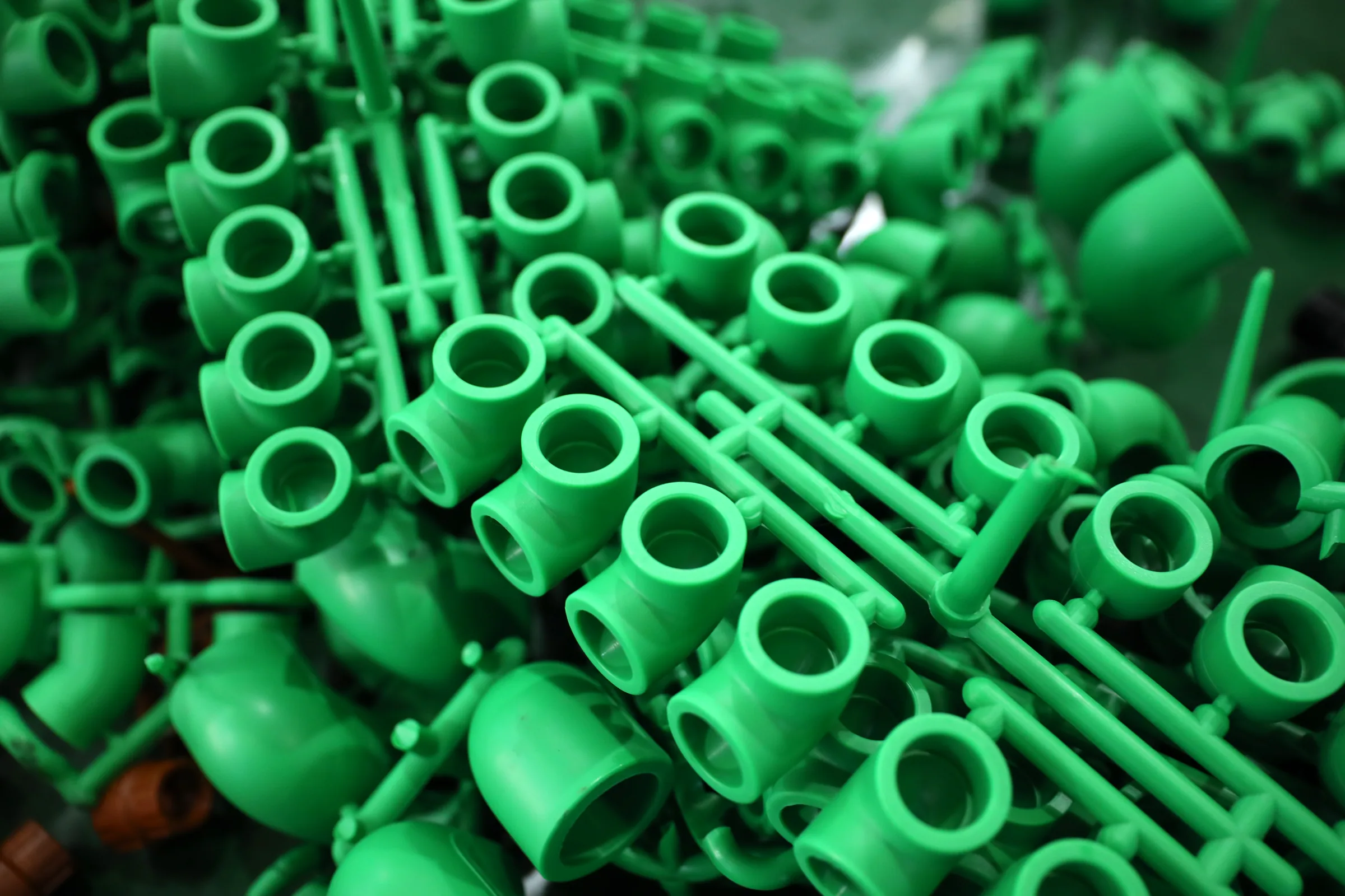
Search traffic for PPR and HDPE sizing is heavily inch-based, so this needs saying directly. When a Gulf contractor asks for “3/4 inch PPR”, they are almost never asking for a pipe whose outside diameter is 19.05 mm. They are using inch shorthand for a trade size on a metric line.
The honest answer is that there is no standard conversion, because ISO/DIS 6708 states there is no direct dimensional correspondence between DN, NPS and A series, and ISO 161-1 sizes are metric-native. Any “PPR inch equivalent” chart you find online is a trade convention, not a standards-derived conversion. What we can publish without inventing anything is our actual manufactured PPR range with straight arithmetic mm-to-inch conversion of the real outside diameter, labelled as arithmetic rather than a designation.
| PPR pipe (per our catalogue) | Actual OD (mm) | Wall (mm) | OD converted arithmetically (in) | Length | Class |
|---|---|---|---|---|---|
| 20 × 2.8 | 20 | 2.8 | 0.787 | 4 m | PN20 |
| 25 × 3.5 | 25 | 3.5 | 0.984 | 4 m | PN20 |
| 32 × 4.4 | 32 | 4.4 | 1.260 | 4 m | PN20 |
| Above 32 mm | Not manufactured on this line — the PPR range is these three sizes, not a truncated series | ||||
Sizes and walls per our catalogue; the inch column is arithmetic conversion of the stated OD (25.4 mm per inch), not an NPS designation. Note that 25 mm converts to 0.984 in, which is why it gets called “1 inch” in the trade — but NPS 1 steel pipe is 33.4 mm OD (ASME B36.10M-2004, Table 1). The two things called “1 inch” differ by 8.4 mm in outside diameter.
The one genuinely inch-designated line in our range is brass 2405 at 1/4 in to 1 in (per our catalogue). Threaded brass is a legitimately different case: ISO 6708:1980 excludes components designated by thread size from nominal size designation, and ISO 161-1 clause 3.1.1 makes the same carve-out. Thread form and per-size dimensional data for our 2405 range: Coming soon.
SDR has a one-line definition and almost everything else said about it is derived. ISO 4427-1:2007 clause 3.1.1.15 defines it as “standard dimension ratio SDR — ratio of the nominal outside diameter, dn, of a pipe to its nominal wall thickness, en“. So SDR = dn / en.
Two things follow. SDR uses the nominal outside diameter, so it is only meaningful for OD-controlled pipe — which is what ISO 161-1 metric plastics pipe and our own lines are. And a lower SDR means a thicker wall relative to diameter, because the diameter is on top of the fraction: SDR 11 is heavier-walled than SDR 17. Buyers routinely get this backwards.
The Plastics Pipe Institute states the consequence that matters commercially: “the pressure rating remains the same for the same material, dimension ratio and application” regardless of diameter, and there is roughly a 25% difference in minimum wall thickness between successive SDR steps (PPI, HDPE Standard Dimension Ratio advisory). That is why SDR exists — one ratio number carries a pressure rating across a whole diameter range, which a wall thickness in millimetres cannot do.
You can verify SDR = dn / en against the official tables. At nominal size 400 mm in ISO 4427-2:2007 Table 2: SDR 21 has emin 19.1 mm (400/19.1 = 20.94); SDR 26 has emin 15.3 mm (400/15.3 = 26.14); SDR 41 has emin 9.8 mm (400/9.8 = 40.82). The computed ratios land near but not exactly on the nominal SDR because the tabulated wall is a minimum with a tolerance band above it (ISO 4427-2:2007, Table 2, DN 400 row).
There is a companion designation, pipe series S, defined in ISO 4065. ISO 4427-1 gives the exact relationship: “S = (SDR − 1) / 2” (ISO 4427-1:2007, clause 3.1.1.14, note). That formula reproduces all ten pairs in the ISO 4427-2 Table 2 headers exactly.
| SDR (ISO series) | Pipe series S | Check: (SDR − 1) / 2 | Relative wall |
|---|---|---|---|
| SDR 6 | S 2.5 | 2.5 | Thickest |
| SDR 7.4 | S 3.2 | 3.2 | ↑ |
| SDR 9 | S 4 | 4.0 | ↑ |
| SDR 11 | S 5 | 5.0 | ↑ |
| SDR 13.6 | S 6.3 | 6.3 | middle |
| SDR 17 | S 8 | 8.0 | ↓ |
| SDR 21 | S 10 | 10.0 | ↓ |
| SDR 26 | S 12.5 | 12.5 | ↓ |
| SDR 33 | S 16 | 16.0 | ↓ |
| SDR 41 | S 20 | 20.0 | Thinnest |
SDR/S pairs from ISO 4427-2:2007 Table 2 headers; relationship from ISO 4427-1:2007 clause 3.1.1.14. ISO 4065 is the standard that owns the universal wall thickness table relating en to dn. The full ISO 4065 wall thickness table itself we were unable to obtain from an accessible official source, so per-size wall values from that table are not reproduced here.
This is a direct substitution trap and it appears on real purchase orders. There are two SDR number series in circulation and they are not the same list.
| ASTM / PPI series | ISO 4427-2 series | Status |
|---|---|---|
| — | 41 | ISO only |
| 32.5 | 33 | Different numbers |
| 26 | 26 | Common to both |
| 21 | 21 | Common to both |
| 17 | 17 | Common to both |
| 13.5 | 13.6 | Different numbers, different walls |
| 11 | 11 | Common to both |
| 9 | 9 | Common to both |
| 7.3 | 7.4 | Different numbers, different walls |
ASTM/PPI series from the PPI HDPE SDR advisory; ISO series from ISO 4427-2:2007 Table 2 headers. ASTM SDR 13.5 and ISO SDR 13.6 are not typos of one another — they are different ratios and therefore different wall thicknesses. Same for ASTM 7.3 versus ISO 7.4.
The diameter basis diverges too. ASTM D3035 covers PE pipe “based on controlled outside diameter” in “thermoplastic pipe dimension ratios based on outside diameter IPS 1/2 to 3”, and hands off larger sizes: “for DIPS sizes and larger sizes refer to the appropriate standard specification such as Specification F714 or AWWA C906” (ASTM D3035-22, scope). So “SDR 11 HDPE” with no statement of IPS, DIPS or ISO metric leaves the outside diameter undefined — three different pipes satisfy that description.
How far apart are they? DIPS outside diameters are 4.800 in at 4 in, 6.900 in at 6 in, 9.050 in at 8 in, 13.200 in at 12 in and 25.800 in at 24 in (Chevron Phillips Chemical, Bulletin PP 153-4710). Against the IPS/steel outside diameters in ASME B36.10M-2004 (4.500, 6.625, 8.625 and 12.750 in), the gaps are +7.6 mm at 4 in, +7.0 mm at 6 in, +10.8 mm at 8 in and +11.4 mm at 12 in. A 4 in DIPS fitting will not fuse to 4 in IPS pipe.
Our HDPE is ISO-metric OD, Φ20–Φ110, with 603/604 compression fittings (per our catalogue). If you are mixing our metric pipe with North American stock on the same site, it will not connect without a transition.
PN is where the two engineering traditions diverge most confusingly, because the same two letters mean different things in the flange world and the plastics world.
In the European flange world, EN 1333:2006 clause 2.1 defines PN as an “alphanumeric designation used for reference purposes related to a combination of mechanical and dimensional characteristics of a component of a pipework system.” The notes then remove any pressure reading: “the number following the letters PN does not represent a measurable value and should not be used for calculation purposes except where specified in the relevant standard” (Note 1), and “the designation PN is not meaningful unless it is related to the relevant component standard number” (Note 2). Note 3 adds that “the maximum allowable pressure of a pipework component depends on the PN number, the material and design of the component, its maximum allowable temperature, etc.”
In the plastics world, PN is closer to a pressure. ISO 4427-1:2007 clause 3.1.2.1 defines nominal pressure PN as a “numerical designation used for reference purposes related to the mechanical characteristics of the component of a piping system”, with the note that “for plastic piping systems conveying water, it corresponds to the maximum continuous operating pressure, expressed in bar, which can be sustained with water at 20 °C, based on the minimum design coefficient”.
So for our UPVC/CPVC 806 and HDPE lines, PN 16 means 16 bar continuous with water at 20 °C (per our catalogue for the class; ISO 4427-1:2007 clause 3.1.2.1 for the meaning of the designation). For an EN 1333 metal flange, PN 16 is expressly not a measurable value. Same notation, different semantics.
The permitted PN values in EN 1333:2006 clause 3 are PN 2.5, 6, 10, 16, 25, 40, 63, 100, 160, 250, 320 and 400 — twelve values. Note that PN 20 and PN 50 are not on the EN flange list, even though PN 20 appears routinely in plastics contexts (our PPR line is PN20, per our catalogue) and PN 20/PN 50 turn up in ASME-derived contexts. If a specification says “PN 20 flange to EN 1333”, something is wrong with the specification.
ISO 4427-1:2007 clause 3.1.2.2 gives the only authoritative bridge between SDR and pressure:
MOP = 20 × MRS / (C × [SDR − 1]), where MOP is maximum operating pressure in bar, MRS is minimum required strength in MPa, and C is the overall service (design) coefficient (ISO 4427-1:2007, clause 3.1.2.2).
Read the variables. Pressure depends on SDR and material grade and design coefficient — never on SDR alone. That is why “SDR 11 = PN 16” is a half-truth.
The material grades come from ISO 4427-1 Table 3: PE 100 has MRS 10.0 MPa giving design stress σs 8.0 MPa; PE 80 has MRS 8.0 → 6.3; PE 63 has MRS 6.3 → 5.0; PE 40 has MRS 4.0 → 3.2. “Design stress, σs, is derived from the MRS by application of the overall service (design) coefficient, C = 1.25″ for water (ISO 4427-1:2007, Table 3 and clauses 3.1.3.1–3.1.3.4).
Every value in the table below is from ISO 4427-2:2007 Table 2.
| SDR | PE 100 | PE 80 | PE 63 | PE 40 |
|---|---|---|---|---|
| SDR 7.4 | PN 25 | PN 20 | — | PN 10 |
| SDR 9 | PN 20 | PN 16 | — | PN 8 |
| SDR 11 | PN 16 | PN 12.5 | PN 10 | — |
| SDR 17 | PN 10 | PN 8 | — | PN 4 |
| SDR 21 | PN 8 | PN 6 | — | — |
| SDR 26 | PN 6 | PN 5 | PN 4 | PN 2.5 |
| SDR 33 | PN 5 | — | — | — |
| SDR 41 | PN 4 | — | — | — |
All PN values from ISO 4427-2:2007 Table 2, in bar. Read across the SDR 11 row: identical geometry, identical wall-to-diameter ratio, and the pressure class swings from PN 16 on PE 100 to PN 12.5 on PE 80 to PN 10 on PE 63. A buyer who orders “SDR 11, PN 16” without stating the resin grade has written a self-contradictory line if the mill runs PE 80.
The formula reproduces the table, so you can check any supplier’s claim yourself. Computing MOP = 20 × MRS / (C × (SDR − 1)) with C = 1.25: PE 100 (MRS 10) at SDR 11 gives 16.00 bar against the tabulated PN 16; SDR 17 gives 10.00 bar against PN 10; SDR 7.4 gives 25.00 bar against PN 25. PE 80 (MRS 8) at SDR 11 gives 12.80 bar against PN 12.5; SDR 9 gives 16.00 bar against PN 16. Every value matches the ISO 4427-2 table once rounded down to the R20 PN class (arithmetic check of ISO 4427-1 clause 3.1.2.2 against ISO 4427-2 Table 2).
One more trap on the pressure side: North American PE pipe is rated in psi on a different basis entirely. Chevron Phillips publishes PE4710 DIPS at DR 7.0 = 335 psi, DR 9.0 = 250 psi, DR 11.0 = 200 psi, DR 13.5 = 160 psi, DR 17.0 = 125 psi, DR 21.0 = 100 psi and DR 32.5 = 63 psi, on the stated basis that “pressure ratings are calculated using 0.63 design factor for HDS at 73°F as listed in PPI TR-4 for PE 4710 materials” (Chevron Phillips, Bulletin PP 153-4710). That is a 73 °F / design-factor basis against ISO’s 20 °C / C = 1.25 basis. So DR 11 is 200 psi (about 13.8 bar) there, while ISO PE 100 SDR 11 is PN 16 — same geometry, different declared rating.
Every PN figure on this page, including our own PN16 and PN20 classes, is a 20 °C declaration. Hot service reduces the allowable pressure and this is not optional engineering judgement — it is tabulated.
ISO 4427-1:2007 Annex A Table A.1 gives pressure reduction coefficients for PE 80 and PE 100: 1.00 at 20 °C, 0.87 at 30 °C, 0.74 at 40 °C. Allowable operating pressure PFA = fT × fA × PN, where fT is the temperature coefficient and fA = 1 for conveyance of water. Above 40 °C, the standard requires that the compound manufacturer be consulted (ISO 4427-1:2007, Annex A).
| Service temperature | Coefficient fT (PE 80 / PE 100) | PN 16 pipe → allowable pressure |
|---|---|---|
| 20 °C | 1.00 | 16.0 bar |
| 30 °C | 0.87 | 13.9 bar |
| 40 °C | 0.74 | 11.8 bar |
| Above 40 °C | Consult compound manufacturer (ISO 4427-1 Annex A) | Not tabulated |
Coefficients from ISO 4427-1:2007 Annex A Table A.1; the PN 16 column is PFA = fT × PN with fA = 1 for water. This matters in the Gulf, where buried and rooftop water lines do not sit at 20 °C for much of the year. A PN 16 PE 100 line at 40 °C service is effectively an 11.8 bar line — so if your design working pressure is 14 bar, PN 16 looks like adequate margin and is not.
Equivalent derating coefficients for our UPVC/CPVC 806 PN16 and PPR PN20 lines are not tabulated in our catalogue, so ask for them on enquiry. What the catalogue does state is the class, the full per-size wall (published above), and that the UPVC/CPVC 806 system withstands 95–120 °C and resists acids and alkalis — note that the heat-resistance description belongs to the CPVC grade of the 806 system, not to UPVC on its own. What it does not carry is a temperature/pressure derating table, and we are not going to transfer the PE coefficients onto a different polymer.
You will meet schedule numbers whenever steel or imported North American plastic pipe enters the scope. Schedule is not a wall thickness and not a pressure rating. The same schedule gives a different wall at every NPS, verified from ASME B36.10M-2004 Table 1.
| NPS | Schedule 40 wall (mm) | Schedule 80 wall (mm) |
|---|---|---|
| NPS 1 | 3.38 | 4.55 |
| NPS 2 | 3.91 | 5.54 |
| NPS 4 | 6.02 | — |
| NPS 6 | 7.11 | 10.97 |
| NPS 8 | 8.18 | 12.70 |
All values from ASME B36.10M-2004 Table 1. Schedule 40 varies from 3.38 mm to 8.18 mm across these five sizes alone. ASME adds that for pressure the designer “shall compute the exact value of wall thickness suitable for conditions” per ASME B31 or the BPVC — schedule alone does not define a rating (ASME B36.10M-2004, Clause 9).
There is a second trap: STD/XS and Schedule 40/80 are identical only up to a size limit. ASME B36.10M Clause 8 states: “Standard and Schedule 40 are identical for up to NPS 10 (DN 250), inclusive. All larger sizes of Standard have 3/8 in. (9.53 mm) wall thicknesses. Extra-Strong and Schedule 80 are identical for up to NPS 8 (DN 200), inclusive. All larger sizes of Extra-Strong have 1/2 in. (12.70 mm) wall thicknesses.” Verified in Table 1: at NPS 12, STD is 9.53 mm while Sch 40 is a separate heavier row; at NPS 14, STD is 9.53 mm and is listed as Sch 30, not Sch 40 (ASME B36.10M-2004, Clause 8 and Table 1). Anyone ordering “Sch 40” above NPS 10 assuming it equals STD has ordered the wrong pipe.
Our own lines carry no schedule designation. UPVC/CPVC 806 and HDPE are PN-rated OD-controlled metric pipe (per our catalogue). If a specification asks for a schedule number on plastic pipe, it is either specifying ASTM-series pipe we do not make, or the specification has been copied from a steel section without editing.
The most expensive version of the DN/NPS confusion happens at flanged connections, because two flanges can carry nominally equivalent designations and still not bolt together.
At NPS 6 / DN 150, an ASME B16.5 Class 150 flange has an outside diameter of 279.4 mm against 285 mm for an EN 1092-1 PN 16 flange; bolt circles are 241.3 mm versus 241.0 mm; both have 8 bolts at around M20 / 3/4 in. In some sizes (NPS 2 / DN 50, NPS 4 / DN 100) the bolt holes align well enough for field mating; in others they do not and the flanges are physically incompatible. Gaskets differ too — ASME B16.20 and EN 1514-2 gaskets are not interchangeable — and material certification follows ASTM versus EN 10222. Recommended practice is to avoid mixing ASME and EN flanges in one system, or to use a transition spool (Projectmaterials, Class 150 vs PN16 comparison).
An honesty note on those millimetre figures: ASME B16.5 and EN 1092-1 are both paywalled and we could not open either text, so the dimensions above come from an industry reference rather than the standards. The direction of the conclusion matches engineering consensus, but verify the numbers against the two standards before using them on a drawing or quotation.
Flanged connections are outside our supply scope in any case. Our UPVC and HDPE ranges connect by solvent cement, compression fitting and threaded transition (per our catalogue). Flange adaptor availability and dimensions: Coming soon.
This is the table to print or save. It puts every IFANNova product line against its designation system, real dimensional basis and class, so you can check in one place whether an incoming specification is answerable from our range.
| Line | Designation system | Is the number the real OD? | Range (per our catalogue) | Class | Jointing | Above range |
|---|---|---|---|---|---|---|
| PPR 1103 pipe / 1138 fittings | Metric dn, ISO 161-1 style | Yes — 20 mm means 20 mm OD | 20 × 2.8, 25 × 3.5, 32 × 4.4 mm, × 4 m | PN20 | Socket (heat) fusion (per our catalogue) | Not manufactured above 32 mm |
| UPVC / CPVC 806 / WP55 pipe, 1806 fittings | Metric dn | Yes | Φ20 × 2.0 to Φ110 × 7.2 mm, nine sizes, × 4 m | PN16 | Solvent cement; 203 fittings incl. ball valves and cement, Φ20–Φ110 (per our catalogue) | Not manufactured above Φ110 |
| HDPE pipe, 603 / 604 fittings | Metric dn; pipe marked DIN 8077/8078 (per our catalogue) | Yes | Φ20 × 2.3 to Φ110 × 10.0 mm, nine sizes | PN16 | Compression, no fusion required, Φ20–Φ110 (per our catalogue) | Not manufactured above Φ110 |
| PVC 902 drainage pipe / 1902 fittings | Metric dn | Yes | Pipe Φ32 × 1.6 to Φ110 × 2.2 mm, nine sizes, × 4 m; 1902 fittings to Φ160 | Non-pressure | Solvent cement drainage fittings | Pipe not made above Φ110; non-pressure duty only — never substitute for a PN-rated line |
| PEX 2114 sliding sleeve | Series designation S16 / S20 | Per series | S16, S20 | Not listed in our catalogue — confirm on enquiry | Sliding sleeve (per our catalogue) | Wall not listed in our catalogue |
| PEX 2121 press | Metric mm | Yes | 16, 18, 20, 25, 26, 32 mm | Not listed in our catalogue — confirm on enquiry | Press fitting (per our catalogue) | Wall not listed in our catalogue |
| Brass 2405 fittings and valves | Thread size, inches — excluded from DN designation per ISO 6708:1980 | No — thread designation, not a diameter | 1/4 in – 1 in | Per fitting | Threaded | Thread form data: Coming soon |
Two rows deserve a second look. The PVC 902 row reaches Φ160 in the 1902 fitting range while the 902 pipe itself stops at Φ110, as does every pressure line — a larger number on a non-pressure product, and one that exists only in fittings, which is precisely the kind of thing that gets mis-substituted when someone is scanning a price list for “the 160”. And the brass row is inch-designated because it is thread-designated, which ISO 6708:1980 explicitly excludes from nominal size designation. It is not an imperial version of the metric range.
We would rather say this on a public page than in the third email of a quotation round. Our pressure pipe production ceiling is Φ110 for UPVC/CPVC 806 and HDPE, and 32 mm for PPR; PVC 902 drainage pipe also stops at Φ110, with only the 1902 fittings reaching Φ160 (per our catalogue). We do not supply DN 150–400 distribution mains. Any supplier telling you they can handle your full system from terminal branch to plant room main should be asked to show the size range in writing.
Practically, our range covers terminal branches, riser take-offs, fixture and equipment connections, and small-diameter distribution. It does not cover primary and secondary distribution mains, transmission mains, or large-bore municipal work. If your enquiry mixes both, split it: send us the portion at Φ110 and below and source the mains elsewhere.
On insulation: we can supply insulation alongside the pipe. Material, thickness and vapour barrier specification: Coming soon, advised per project. We do not publish an insulation specification because we do not have a product datasheet for one.
Is DN 100 the same as 110 mm HDPE? No. Steel DN 100 is 114.3 mm OD (ASME B36.10M-2004, Table 1). Our Φ110 HDPE is 110 mm OD (per our catalogue; ISO 161-1:2018 Table 1). They differ by 4.3 mm and belong to different designation systems — ISO/DIS 6708 clause 3 states there is no direct dimensional correspondence between DN and other series.
How many mm is 1 inch of PPR pipe? There is no standards-defined answer: PPR is designated by metric outside diameter, and inch designations belong to a different, non-corresponding series (ISO/DIS 6708, Clause 3). In the trade, 25 mm PPR is commonly called “1 inch” — its actual OD is 25 mm, or 0.984 in arithmetically (per our catalogue). NPS 1 steel pipe is 33.4 mm OD (ASME B36.10M-2004), a different pipe entirely.
What are the standard PPR pipe sizes you make? Three: 20 × 2.8, 25 × 3.5 and 32 × 4.4 mm, in 4 m lengths, PN20 (per our catalogue). That is the whole line — above 32 mm we do not make PPR at all, which is a range limit rather than a gap in our published data.
Does SDR 11 mean PN 16? Only on PE 100. On PE 80 the identical SDR 11 pipe is PN 12.5, and on PE 63 it is PN 10 (ISO 4427-2:2007, Table 2). SDR is a geometry ratio, dn/en (ISO 4427-1:2007, clause 3.1.1.15); pressure additionally requires the material grade and design coefficient (ISO 4427-1:2007, clause 3.1.2.2).
Is a lower SDR a stronger pipe? Lower SDR means a thicker wall relative to diameter, since SDR = OD / wall. Whether that translates to a higher pressure class still depends on the resin grade, per the table above.
What is the largest pipe you can supply, and do you make DN 200–300 mains? Φ110 for pressure pipe in UPVC/CPVC 806 and HDPE; 32 mm for PPR; and for drainage, 902 pipe to Φ110 with 1902 fittings up to Φ160 (per our catalogue). Nothing above that, so DN 200 and DN 300 mains are outside our range.
Can I use your metric HDPE with North American IPS or DIPS fittings? Not without a transition. IPS and DIPS outside diameters differ from each other by 7.0–11.4 mm at 4–12 in (Chevron Phillips Bulletin PP 153-4710 against ASME B36.10M-2004), and both differ from the ISO metric series. Our fittings are the 603/604 compression series matched to our own metric pipe (per our catalogue).
What do your certificates cover? Our catalogue lists German SKZ, CE, WRAS, DVGW, SGS and ISO 9001/14001 among others (per our catalogue). Certificate numbers, validity dates and exact scope: Coming soon — we send current documents against a specific enquiry rather than publish figures we cannot keep current.
Do you have a downloadable version of these charts? A consolidated PDF of the size tables on this page is available now: download the IFANNova Pipe Size Chart (PDF). It carries the same figures as this page — the full per-size wall tables for PPR, UPVC/CPVC 806, HDPE and PVC 902, and “confirm on enquiry” on the PEX wall, which our catalogue does not list. The tables above are the complete set of size data we can source to our catalogue.
MOQ, lead time and pricing? Coming soon — quoted per enquiry.
Where are your products made? IFANNova is a French brand working to European design standards. Manufacturing is in our own facility by Zhuji Fengfan Piping Co., Ltd in Zhejiang, China (per our catalogue): 30+ years, 1000+ employees, exports to 118+ countries, 10,000 sets of moulds, 120,000 m² of plant, 24h online service.
Given everything above, a size alone is not enough information to quote against. Send these five items and you will get a usable reply rather than a clarification round:
And one filter to apply before you write: if the largest size on your list is above Φ110, or above 32 mm on PPR, that portion is outside our range (per our catalogue). Tell us the split and we will quote what we actually make.
Two pages, no email required: the manufactured range across all six systems, the three designation traps that cost buyers money, and the five inputs that get you a straight answer on an enquiry. Same discipline as this page — the full per-size wall tables where our catalogue publishes them, and “confirm on enquiry” on the one line where it does not.
Charts settle what a designation means. They do not settle whether the pipe on your drawing is the pipe we make. Send the five inputs below and you get a written answer against our actual range — including a straight “no” where the size sits above our ceiling.
The metric range we actually manufacture, with the catalogue wall thickness for every one of the nine sizes we make, and a clear statement of where the range stops.
Our PPR line is three sizes deep.
Our catalogue states a wall thickness for every diameter we make.
