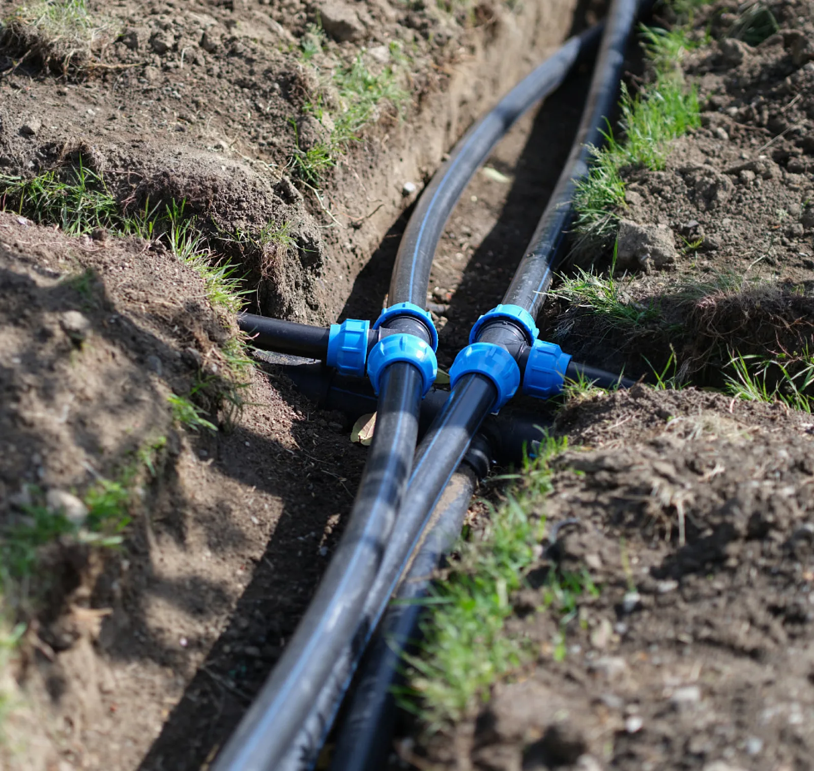
A butt fusion weld is the only part of an HDPE system that is manufactured on site. The pipe was extruded under process control in a factory. The fitting was moulded. The joint was made by a person standing in a trench, using a machine whose gauge does not read the number that actually matters, following a procedure whose most critical step is defined by the absence of pressure rather than its presence.
That asymmetry explains why joint failure dominates the failure conversation while the pipe itself rarely appears in it. And it explains a fact that should shape how you inspect: a DOE/NETL-funded study by EWI reports that cold joints — a weak interface bond between the pipe ends being joined — account for the majority of butt fusion failures experienced in the field, and that the ultrasonic tools evaluated could not detect them. The McElroy UltraMac’s major limitation was that it could not detect cold joints; per NYSEARCH and the ultrasonic experts consulted, this defect type “cannot be detected due to ultrasonic technology limitations” even with time-of-flight diffraction (DOE/NETL — EWI, Inspection of Fusion Joints, Final Report NT41882, clause 3.2.1).
Read that twice. The failure mode that causes most field failures is the one your NDE cannot find. The same report is equally blunt about the fallback: visual inspection “can be useful at times, but it is not foolproof,” there are joint defects that can only be observed by applying some form of technology, and visual examination “should be considered as a guide or indicator in diagnosing potential problems but does not provide conclusive evidence of future performance” (clause 3.2.2). Destructive examination is reliable — and costly, and of no use whatsoever on a joint already in service.
So the honest position is this: you cannot inspect quality into an HDPE joint. You can only put it in during the eight minutes the weld is being made, and then read the bead afterwards for evidence that you did. This article is organised around the four ways that goes wrong — contamination, insufficient heat, wrong pressure, and disturbed cooling — plus two structural errors that make a joint non-compliant before the heater is even switched on. For each, the mechanism, the published parameter, and the check you can actually verify on site.
A note on scope, stated up front rather than buried. IFANNova’s HDPE pipe and fittings range is Φ20 to Φ110 mm (per our catalogue), and our jointing hardware is the 603 and 604 compression (no-weld) series. We do not supply butt fusion machines, and we do not supply the DN 150–400 mains where butt fusion is most often the only option. This article exists because our pipe gets welded into larger networks by contractors who have to get this right, and because at the small end of the range the parameters are tighter, not looser — see failure mode 3.
These are not failure modes in the process sense. They are decisions taken before heating that put the joint outside the standard regardless of how well it is executed. They belong first because no amount of technique recovers them.
ISO 21307:2017 states it as a “shall not”: “PE components with fusion ends of different SDR/DR values shall not be jointed by butt fusion” (clause 4.1, General). Under that standard a mismatched-SDR butt joint is not a poor-practice joint. It is a non-compliant one, and it is non-compliant at the moment the two ends are clamped, before any parameter is chosen.
The Georg Fischer Butt Fusion Installation and Training Manual takes a different position for its own procedure: the procedure is suitable for components of like polyethylene material with similar melt characteristics, and can be used without change for components of like wall thickness or not exceeding one standard DR difference (for example DR 11 to DR 9); where components of different DR are joined, the fusion pressure/force for the higher DR — the thinner-wall component — is used.
We are not going to pretend these agree. They do not. The manufacturer allowance is more permissive than the standard’s prohibition, and which one governs your joint is a contractual and specification question, not a technical one we can settle for you. Our observation, offered as opinion rather than fact: if your specification calls up ISO 21307, a one-DR-step joint that Georg Fischer’s manual would permit is still a non-conformance against your own spec, and it is the kind that surfaces during a handover audit rather than during commissioning.
The verifiable action: read both fusion ends’ markings before clamping, not after. Record the SDR of each on the fusion log. If the two ends differ because the SDR was specified separately for two sections of the same run, that decision is worth revisiting upstream — see how SDR selection drives wall thickness and cost. Where the joint is unavoidable, resolve it with a transition fitting or an electrofusion coupler rather than by choosing an average parameter.
DVS 2207-1 limits misalignment (high-low) of the joining areas on the pipe outside to a maximum of 0.1 × wall thickness, and states plainly that larger misalignment reduces quality and limits the strength of the joint (clause 4.1.2). Georg Fischer’s field manual states the same limit, expressed as 10% of the pipe minimum wall thickness.
The mechanism is that misalignment does not distribute itself. It concentrates. Where the ends step, the melt zones on the two sides of the interface are asymmetric in depth, so one side gets more mixing than the other around the same circumference. That is why misalignment shows up in the bead as a diagnostic: Georg Fischer’s fusion inspection table maps non-uniform bead size around the pipe and one bead larger than the other to misalignment among their probable causes — alongside defective heating tool, worn equipment, incomplete facing, and (for the asymmetric case) a component that slipped in the clamp.
Because the limit is a fraction of the wall, it shrinks with the pipe. Across our published walls the permitted step runs: Φ110 × 10.0 mm → 1.00 mm; Φ90 × 8.2 → 0.82 mm; Φ75 × 6.8 → 0.68 mm; Φ63 × 5.8 → 0.58 mm; Φ50 × 4.6 → 0.46 mm; Φ40 × 3.7 → 0.37 mm; Φ32 × 3.0 → 0.30 mm; Φ25 and Φ20 × 2.3 → 0.23 mm. Somewhere around Φ50 the tolerance passes below half a millimetre, which is roughly where “eyeball and thumbnail” stops being an inspection method and a feeler gauge or a straightedge becomes the only honest way to sign the line off. This is the first place the small-diameter problem appears, and it will not be the last.
Contamination is the failure mode where the instinctive corrective action is itself an error, which is why it deserves to go first among the four.
Butt fusion works by bringing two melt pools into contact and letting polymer chains from each side interdiffuse across the interface before the material solidifies. Anything sitting on the faced surfaces — hydrocarbon film, dust, moisture, solvent residue — occupies the interface where that interdiffusion has to happen. Some of it volatilises under the heater and leaves voids. Some of it stays and simply prevents chain entanglement over the area it covers. Either way the joint’s load-bearing area is less than its apparent area, and the deficit is invisible in the finished weld’s outside profile.
Georg Fischer’s manual identifies a rough, sandpaper-like, bubbly, or pockmarked melt bead surface as the signature of hydrocarbon contamination. This is the one contamination signature that does present visually — and it presents on the melt bead, at heater removal, not on the finished cooled joint. If nobody is looking at the ends in the two seconds between heater removal and closing, this signal is generated and thrown away.
The same manual directs that faced surfaces must not be cleaned to remove contamination — they must be re-faced if they contacted contamination sources. Wiping a faced surface with a rag moves the contaminant around the surface and presses it into the machined texture; it does not remove it. Facing removes the contaminated layer along with the material under it.
Georg Fischer also warns specifically against denatured alcohol, because its additives can leave residue. That is a genuinely easy mistake: denatured alcohol is cheap, widely available, and its label says alcohol. The additives are the problem.
ISO 21307:2017 requires the heater plate and planing unit surfaces to be cleaned — with a lint-free cloth, a cloth with suitable solvent, or by making dummy joints — whenever the heater plate has been allowed to cool below 180 °C, and at the start of each jointing session, and for a change of pipe size or SDR/DR (clause 4.3).
The 180 °C threshold is the useful part, because it is a trigger you can instrument rather than a judgement call. Above it, residue on the plate is in a state where it does not accumulate the same way. Let the plate drop below it — a lunch break, a generator that cut out, a move between trench sections — and the re-clean or dummy-joint requirement is live. Most site arguments about “does this plate need cleaning” are resolvable by looking at the plate’s own temperature history.
| Contamination check | Requirement / signature | Source |
|---|---|---|
| Heater plate re-clean trigger | Plate allowed to cool below 180 °C; also start of each session, and change of pipe size or SDR/DR | ISO 21307:2017, clause 4.3 |
| Permitted cleaning methods (plate & planing unit) | Lint-free cloth, cloth with suitable solvent, or dummy joints | ISO 21307:2017, clause 4.3 |
| Faced pipe end that touched a contamination source | Re-face. Do not clean the faced surface. | Georg Fischer Butt Fusion Installation and Training Manual |
| Denatured alcohol as a cleaner | Avoid — additives can leave residue | Georg Fischer Butt Fusion Installation and Training Manual |
| Rough / sandpaper-like / bubbly / pockmarked melt bead | Signature of hydrocarbon contamination | Georg Fischer Butt Fusion Installation and Training Manual |
This is the failure mode behind the statistic at the top of this article: the cold joint that dominates field failures and that ultrasonic inspection cannot find.
The distinction that matters is between melting the surface and melting to depth. ISO 21307:2017 defines heat soak as the portion of the heating cycle performed at 0 to drag pressure, so that heat can melt the pipe to a depth sufficient for proper mixing and fusion (clauses 3.9–3.11).
Read the purpose clause carefully: the soak exists to create depth. A surface that is molten to half a millimetre will still produce a bead when you close the machine. It will produce a bead that looks broadly right. What it will not produce is a melt pool deep enough for the interdiffusion zone to carry load. That is the cold joint, and it is why the defect is simultaneously the most common and the least detectable: geometrically the joint is complete, and the deficiency is in the molecular state of an interface a few millimetres inside the wall.
Two standards families give two different heater temperature ranges, and both are correct within their own system:
| Parameter | DVS 2207-1 (European) | PPI TR-33 (North American) |
|---|---|---|
| Heated tool / heater surface temperature | 200–220 °C for PE-HD | 400–450 °F (204–232 °C) |
| Which end of the range | Upper limit for smaller wall thicknesses, lower limit for larger wall thicknesses; upper limit also to be chosen for PE 100 | Single range stated for pipe meeting ASTM F714, ASTM D3035, AWWA C-901 and AWWA C-906 |
| Interfacial / joining pressure | Joining p = 0.15 ± 0.01 N/mm² (= 1.5 bar = 21.7 psi) | 60–90 psi (4.14–6.21 bar) |
| Heating (soak) pressure | Reduced to nearly zero, p ≤ 0.01 N/mm² | Except for very brief seating contact, pressure must not be applied during heating |
The DVS rule about which end of the range to use is worth isolating, because it inverts the intuition. Upper limit (220 °C) for smaller wall thicknesses; lower limit for larger. A thin wall has less thermal mass and a shorter path for heat to travel; the higher plate temperature drives soak depth quickly before the thin section over-melts through. A thick wall held at 220 °C would degrade its surface long before the centre reached soak depth. DVS also states explicitly that the upper temperature is to be chosen for PE 100 (clause 4.1.3).
DVS 2207-1’s Table 2 gives heating-up time as a function of nominal wall thickness s, and the relationship is arithmetic: heating-up time in seconds = 10 × wall thickness in millimetres. Table 2’s values are stated for PE-HD at approximately 20 °C ambient with moderate air flow, with interim values interpolated. Selected rows:
| Wall thickness s (mm) | Bead height at end of alignment (mm) | Heating-up time (s) | Changeover time (s) | Joining pressure build-up (s) | Cooling time under joining pressure (min) |
|---|---|---|---|---|---|
| up to 4.5 | 0.5 | up to 45 | 5 | 5 | 6 |
| 7 – 12 | 1.5 | 70 – 120 | 6 – 8 | 6 – 8 | 10 – 16 |
| 19 – 26 | 2.5 | 190 – 260 | 10 – 12 | 11 – 14 | 24 – 32 |
| 50 – 70 | 4.0 | 500 – 700 | 20 – 25 | 25 – 35 | 60 – 80 |
Source: DVS 2207-1 (English), clause 4.1.3 and Table 2. Conditions: PE-HD, approximately 20 °C ambient, moderate air flow; interim values interpolated.
Because the rule is arithmetic on wall thickness, it resolves to a specific number for every size we supply. Our catalogue publishes the wall for all nine diameters — the same figures set out in the HDPE pipe diameter chart — so the whole column below is computed rather than estimated:
| IFANNova HDPE size (PN16) | Wall s (mm) | DVS heating-up time ≈ 10 × s (s) | DVS Table 2 band | Cooling under joining pressure (min) |
|---|---|---|---|---|
| Φ20 | 2.3 | ≈ 23 | up to 4.5 mm | 6 |
| Φ25 | 2.3 | ≈ 23 | up to 4.5 mm | 6 |
| Φ32 | 3.0 | ≈ 30 | up to 4.5 mm | 6 |
| Φ40 | 3.7 | ≈ 37 | up to 4.5 mm | 6 |
| Φ50 | 4.6 | ≈ 46 | 4.5 – 7 mm | 6 – 10 |
| Φ63 | 5.8 | ≈ 58 | 4.5 – 7 mm | 6 – 10 |
| Φ75 | 6.8 | ≈ 68 | 4.5 – 7 mm | 6 – 10 |
| Φ90 | 8.2 | ≈ 82 | 7 – 12 mm | 10 – 16 |
| Φ110 | 10.0 | ≈ 100 | 7 – 12 mm | 10 – 16 |
Diameters and walls per our catalogue; heating times are the DVS 2207-1 arithmetic applied to those walls, and the band and cooling columns are read off DVS Table 2. Treat them as the starting point your machine manufacturer’s procedure and your project specification then govern — not as a substitute for either.
Two things follow. First, the whole range spans roughly 23 to 100 seconds of heating and 6 to 16 minutes of cooling — a factor of four in heating time across nine sizes, which is why a single procedure card covering “small HDPE” is not a procedure card. Second, and more important: a 2.3 mm wall gives you about 23 seconds of heating time. There is no margin in that number for a distracted operator, and the penalty for guessing is on the low side, which is the cold-joint side.
PPI TR-33 documents that ASTM F2620-11e1 added a minimum heat soak time of 4.5 minutes per inch of wall thickness for pipe sizes 14 in and larger, alongside changing the cool time under fusion pressure from 30–90 seconds per inch of pipe diameter to 11 minutes per inch of wall thickness, and establishing a maximum open/close (dwell) time by wall thickness.
One sourcing caveat we will state rather than hide: we were unable to open ASTM F2620 itself — it is paywalled and no accessible full text was found. Those values are reported here only as documented inside PPI TR-33, which explicitly describes them as the F2620-11e1 changes. If you need to cite them in a specification or a method statement, buy F2620 and cite it directly. Do not cite it on the strength of this article.
Georg Fischer’s fusion inspection table maps beads too small to insufficient heating or insufficient joining force, and beads too large to excessive heating time. That “or” matters: a small bead does not by itself tell you which parameter was wrong. You need the other bead characteristics — profile shape, edge geometry, groove depth — to separate a heat problem from a pressure one. Which is exactly what the next section is about.
Pressure produces more genuine confusion than any other parameter in butt fusion, for two reasons: the number on the gauge is not the number in the standard, and the two major standards families disagree by a factor of four.
PPI TR-33 is explicit: “Interfacial pressure and gauge reading are not the same value.” The fusion force is interfacial pressure (60–90 psi) multiplied by the pipe area; that force divided by the total effective piston area gives a theoretical gauge reading; and to that theoretical reading the internal and external drags must be added to obtain the actual required machine pressure. The gauge reading therefore depends on pipe diameter, on DR, and on the design of the specific machine.
ISO 21307:2017 encodes the same physics in its definitions. Drag pressure is the gauge pressure required to overcome the sliding frictional drag force of the machine and pipe — and the standard notes it may be a positive or a negative value (ISO 21307:2017 clause 3.5, including Note 1 to entry). A negative drag is not a rounding artefact; it is what a machine on a downslope, or with the pipe weight assisting the carriage, actually produces.
The practical consequence: a drag reading taken once in the morning and used all day is a systematic error that grows as the day changes. Add a hundred metres of pipe to the string, move to a slope, let the trench get muddy, and the drag has changed. Every joint made against the stale figure is made at an interfacial pressure nobody measured.
DVS 2207-1 specifies three distinct pressure levels for PE-HD heated tool butt welding: alignment (bead-up) at p = 0.15 N/mm², heating/soak reduced to nearly zero at p ≤ 0.01 N/mm², and joining at p = 0.15 ± 0.01 N/mm². That 0.15 N/mm² is 0.15 MPa, 1.5 bar, 21.7 psi — roughly a quarter of TR-33’s 60–90 psi.
PPI TR-33 itself supplies the reconciliation, and it is the single most clarifying sentence in the whole pressure literature: TR-33 acknowledges that interfacial fusion pressure recommendations worldwide range from a low of 21.7 psi (1.5 bar) to a maximum of 150 psi (10.34 bar), and that properly conducted fusions across this broad range produce quality fusions that cannot always be differentiated by available testing techniques.
So the answer to “which pressure system is right” is: both, within their own procedure. What is not permissible is mixing them — running DVS heating times with TR-33 pressures, or the reverse. ISO 21307:2017 makes the same structural point by specifying exactly three butt fusion jointing procedures for PE pipes and fittings: single low-pressure, dual low-pressure, and single high-pressure fusion jointing procedures (third edition, 2017-12, prepared by ISO/TC 138/SC 4, cancelling and replacing ISO 21307:2011). Three named procedures, each internally consistent. Choose one and stay inside it.
A scope note, stated so its absence is not read as an oversight: the ISO 21307:2017 numeric parameter tables — the bead-up pressures, soak times, changeover and cooling values for each of the three procedures, given in Tables 1–3 of clause 5 and in Annexes A/B/C — are not reproduced anywhere in this article. They are procedure-specific and should be read in full alongside the clause 5 requirements rather than lifted as isolated numbers. If you need them, buy the standard.
PPI TR-33’s own tensile testing fused two pipe sizes at 425 °F with 25, 40 and 75 psi interfacial pressure. The nominal 75 psi joints had the higher tensile strength before failure. The relative values:
| Interfacial pressure | Pipe 1 (relative tensile strength) | Pipe 2 (relative tensile strength) |
|---|---|---|
| 25 psi | 100% | 100% |
| 40 psi | 104% | 97% |
| 75 psi | 105% | 101% |
Source: PPI TR-33, Part 2 Pipe Fusion and Testing; all fused at 425 °F.
The direction is consistent, the magnitude is within about 5%, and Pipe 2 is not even monotonic. Our reading of that table — offered as interpretation, not as a finding of TR-33 — is that within a validated window, pressure is not the variable that buys you joint strength. It is the variable that, when it is in the wrong place in the cycle, destroys it. Which brings us to the pressure that should not exist.
PPI TR-33 warns that observing a concave melt surface after heater removal indicates unacceptable pressure was applied during heating and the joint will be low quality. The procedure’s instruction is not to compensate. It is to stop, let the ends cool completely, and restart from the beginning. Except for very brief seating contact, pressure must not be applied during heating (clause 5.0, Joining).
The mechanism: pressure during soak squeezes molten material radially out of the interface as fast as it forms. The melt front never advances into the wall, because the melted material keeps leaving. You get a bead — possibly a generous one — over an interface that never soaked. It is the cold joint again, arrived at by a different route, and this time with a visible tell if anyone looks at the ends at heater removal.
Georg Fischer’s inspection table gives two more pressure tells, both readable on the cooled joint: a squarish outer bead edge = pressure during heating, and a third bead = excessive joining force. Their table also flags excessive double bead width as overheating or excessive joining force, flat top on bead as excessive joining force or overheating, and v-groove too deep as excessive joining force, insufficient heating, or pressure during heating.
Both standards families give a groove-depth acceptance criterion, and they are expressed differently but point the same way:
TR-33’s criterion is the tighter of the two in practice — it rejects a groove that has descended halfway to the pipe surface, where DVS’s K > 0 rejects only a groove that has gone below it. Note also what DVS says about asymmetry: bead asymmetry can arise from different melt flow behaviour of the joined materials, and PE 80 / PE 100 within the stated MFR range remain weldable even with asymmetric beads. Asymmetry is a flag to investigate, not an automatic rejection.
PPI TR-33 gives approximate melt bead size at heater removal as a function of pipe size. Because it scales with size, this is one of the few checks that transfers cleanly to a small-diameter range:
| Pipe size | Approximate melt bead size at heater removal |
|---|---|
| 1¼ in and smaller (40 mm and smaller) | 1/32 – 1/16 in (1 – 2 mm) |
| above 1¼ through 3 in (40 – 90 mm) | about 1/16 in (2 mm) |
| above 3 through 8 in (90 – 225 mm) | 1/8 – 3/16 in (3 – 5 mm) |
| above 8 through 12 in (225 – 315 mm) | 3/16 – 1/4 in (5 – 6 mm) |
| above 12 through 24 in (315 – 630 mm) | 1/4 – 7/16 in (6 – 11 mm) |
| above 24 through 36 in (630 – 915 mm) | about 7/16 in (11 mm) |
| above 36 through 63 in (915 – 1600 mm) | about 9/16 in (14 mm) |
Source: PPI TR-33, Table 2, Approximate Melt Bead Size.
IFANNova’s Φ20–Φ110 mm HDPE range (per our catalogue) falls entirely within the first three rows: a melt bead of roughly 1 to 5 mm at heater removal, depending on where in the range you are. On Φ20 that means looking for a 1 mm bead. This is the second place the small-diameter problem bites — the acceptance signal itself is small enough that the difference between “correct” and “half of correct” is under a millimetre, judged by eye, in a trench.
Our position on that, stated as opinion: on pipe at the bottom of the Φ20–Φ110 range, butt fusion asks for a visual discrimination that field conditions do not reliably support. This is a large part of why compression jointing exists at these sizes, and why our 603 and 604 compression fittings are compression rather than fusion systems (per our catalogue). It is not an argument that small-diameter butt fusion is wrong. It is an argument that the inspection you are relying on gets weaker precisely as the pipe gets smaller.
Cooling is the failure mode with the worst incentive structure on a construction site. It is pure waiting, it is the longest phase by far, it produces no visible change, and shortening it appears to cost nothing. The joint disagrees.
DVS 2207-1 requires changeover time — heater out, ends together — to be as short as possible, warning that exceeding it lets the plasticized areas cool down and negatively influences weld joint quality (clause 4.1.3). Table 2’s changeover values run from 5 s at the thinnest walls to 20–25 s at 50–70 mm. For tapping tees, Table 3 sets a maximum changeover time of 10 s and a minimum cooling time under joining pressure of 15 min.
Changeover is where the melt surface is exposed to ambient air and is the only moment in the cycle when the surface that must fuse is both molten and unprotected. A 5-second budget on a thin wall is not a target; it is a constraint that dictates how the tooling and the operator’s hands are arranged before the heater comes out. If the heater has to be walked anywhere, the budget is already gone.
DVS 2207-1 does permit reducing the cooling time under joining pressure by up to 50% — and this is the clause most often quoted without its conditions. It applies only where all three of the following hold at once:
Full mechanical loading is allowed only after complete cooling per Table 2, column 5 (clause 4.1.3, Joining).
Apply that test to a trench and it fails on the first condition. Apply it to our own range and it fails on the third as well: IFANNova’s HDPE tops out at Φ110 × 10 mm (per our catalogue), which is below the 15 mm wall threshold — so the 50% reduction is not available on any pipe we supply, even in a workshop. On a Φ110 × 10 mm joint, DVS Table 2’s 7–12 mm band gives 10–16 minutes of cooling under joining pressure, and there is no compliant route to shortening it.
PPI TR-33 documents that ASTM F2620-11e1 changed the cool time under fusion pressure from 30–90 seconds per inch of pipe diameter to 11 minutes per inch of wall thickness. That is not a tightening of a number. It is a change of the governing variable, from diameter to wall thickness — the same variable DVS Table 2 has always indexed on.
It matters because the two formulations diverge hard on thin-wall large-diameter pipe, which is exactly where a diameter-based rule under-specifies cooling. Anyone still running an inherited pre-2011 procedure card indexed on diameter is running a cooling time that the standard body itself moved away from. (Same caveat as before: this is reported as documented inside PPI TR-33, not read from F2620.)
Cooling defects and pressure defects converge on the same outcome: a void or weak zone at the interface. A peer-reviewed study in Polymers (PMC9571897), testing to EN 12814-3, measured what defect size does to creep life of butt fusion joints. At 40 °C under 9 MPa stress:
| Defect ratio (defect diameter relative to wall thickness) | Creep life at 40 °C / 9 MPa | Retained vs. defect-free |
|---|---|---|
| No defect | ≈ 1,771 h | 100% |
| 16% | ≈ 534 h | ≈ 30% |
| 33% | ≈ 321 h | ≈ 18% |
| 44% | ≈ 163 h | ≈ 9% |
Source: The Effect of Welding Defects on the Long-Term Performance of HDPE Pipes, Polymers, PMC9571897; testing per EN 12814-3. The relationship fitted log(tf) = −0.0223φ + 3.1923. Retained-percentage column is our arithmetic on the study’s stated hours.
Note the shape. A defect occupying 16% of the wall thickness — which is a small feature, and one no visual inspection would flag — took creep life from about 1,771 hours to about 534. The study also found the failure mode shifts: ductile necking in the base material at defect ratios up to 33%, brittle fracture at the joint at 44%. That transition is the meaningful one. Up to 33% the pipe is still failing like a pipe; at 44% it is failing like a bad weld.
The same study found that removing the weld bead cut creep life to about 50% of a joint with the bead retained, tested at 28 °C under 10 MPa. Bead removal is sometimes done for appearance, sometimes to clear an insulation shell or a clamp, sometimes because a specification inherited from another material asked for a flush joint. Whatever the reason, the study measured the cost as roughly half the long-term life. If the bead has to come off for a genuine clearance reason, that is a design decision with a quantified penalty attached — not a housekeeping step.
Set the inspection tools against the failure modes and the picture is uncomfortable but clear.
| Method | Status | Catches | Does not catch | Source |
|---|---|---|---|---|
| Visual examination of the joint | Normative under ISO 21307:2017 clause 6.3 (non-destructive joint integrity testing, with requirements) — newly added in the third edition vs 2011 | Bead geometry faults: groove depth, width ratio, third bead, squarish edge, non-uniform or asymmetric beads, contamination texture on the melt bead | Interface bond quality. “Does not provide conclusive evidence of future performance” | ISO 21307:2017 clause 6.3; DOE/NETL–EWI NT41882 clause 3.2.2 |
| Ultrasonic / TOFD | Evaluated in the DOE/NETL programme | Some volumetric defects | Cold joints — the majority of field failures. Stated as a technology limitation, not a tool limitation | DOE/NETL–EWI NT41882 clause 3.2.1 |
| Destructive examination (incl. bend-back) | Reliable | Interface bond quality directly | Anything about the joints you did not cut; unusable on in-service joints; costly | DOE/NETL–EWI NT41882 clause 3.2.2 |
| Procedural control (parameters + logging) | The only method that acts before the defect exists | Prevents rather than detects | Nothing, if the log is filled in afterwards from memory | Our position |
ISO 21307:2017’s third edition made a change worth registering: it added normative non-destructive joint integrity testing — visual examination with requirements — at clause 6.3, separate from destructive testing at clause 6.2. Under ISO 21307, visual examination is a requirement, not advice. The DOE/NETL report’s warning about its limits and ISO’s decision to make it normative are not in conflict: visual examination is mandatory and insufficient, both at once.
The field destructive check most likely to be available to you: cut the joint into straps, bend each sample at the fusion joint with the inside of the pipe facing out until the ends touch, with an inside bend radius less than the minimum wall thickness of the pipe (a vice may be needed). The sample must be free of cracks and separations within the fusion joint location. Failure at the weld means fusion procedures should be reviewed and corrected. Georg Fischer states this as applicable for wall thickness up to 1 in.
ASTM F3183, Guided Side Bend Evaluation of Polyethylene Pipe Butt Fusion Joint, is the standardised relative of this test. We are referencing it by title only: only the astm.org abstract page was reachable, and we did not verify its acceptance criteria or specimen geometry. Do not quote acceptance criteria for F3183 from this article.
Stated explicitly, because their absence from an article like this is otherwise read as an oversight:
Every line below traces to a source already cited above. This is not a fusion procedure — your machine manufacturer’s procedure and your project specification govern that. It is a checklist of the specific points where the four failure modes enter.
| # | Stage | Check | Governing figure | Failure mode it blocks |
|---|---|---|---|---|
| 1 | Before clamping | Read and log the SDR/DR marking on both fusion ends | ISO 21307:2017 cl. 4.1: different SDR/DR “shall not” be butt fused | Non-compliant joint |
| 2 | Clamping | Measure high-low step on the pipe outside | Max 0.1 × wall thickness (DVS 2207-1 cl. 4.1.2) | Misalignment |
| 3 | Session start / size change / plate below 180 °C | Clean heater plate and planing unit, or make dummy joints | ISO 21307:2017 cl. 4.3 | Contamination |
| 4 | After facing | If a faced end touched a contamination source — re-face it. Do not wipe it. No denatured alcohol. | Georg Fischer manual | Contamination |
| 5 | Every joint, or when conditions change | Re-take drag pressure; note it may be positive or negative | ISO 21307:2017 cl. 3.5 (incl. Note 1 to entry); PPI TR-33 cl. 5.0 | Wrong pressure |
| 6 | Heater set-up | Plate temperature to the chosen system, correct end of the range for wall thickness | DVS: 200–220 °C, upper for thin wall and for PE 100. TR-33: 400–450 °F | Insufficient heat |
| 7 | Bead-up | Bead height at end of alignment matches the wall-thickness band | DVS Table 2: 0.5 mm (≤4.5 mm wall) to 4.0 mm (50–70 mm wall) | Insufficient heat |
| 8 | Heat soak | Drop to soak pressure and hold — heat soak is defined as the portion at 0 to drag pressure | DVS: ≤ 0.01 N/mm². TR-33: no pressure except brief seating | Cold joint |
| 9 | Heat soak | Time the soak against wall thickness, not against the clock in your head | DVS: heating time (s) = 10 × wall (mm) | Cold joint |
| 10 | Heater removal | Look at both melt faces before closing: melt bead size, surface texture, concavity | TR-33 Table 2 bead size; concave = restart; GF: rough/bubbly = hydrocarbon contamination | All four |
| 11 | Changeover | As short as possible, within the Table 2 band for the wall | DVS Table 2 col. 4: 5–25 s; tapping tees max 10 s | Disturbed cooling |
| 12 | Cooling | Hold under joining pressure for the full Table 2 time. 50% reduction requires workshop + low handling loads + wall ≥ 15 mm, all three | DVS cl. 4.1.3 | Disturbed cooling |
| 13 | After cooling | Bead geometry: uniform double bead, K > 0; groove not deeper than half bead height; width ≈ 2–2½ × height; no third bead, no squarish edge | DVS cl. 4.1.3 + Fig. 4; TR-33 cl. 7.0 | All four |
| 14 | Rejection | Visually unacceptable joints are cut out and re-fused | TR-33 cl. 7.0 | — |
| 15 | Whole life | Leave the bead on unless a clearance requirement forces removal | Bead removal ≈ 50% of creep life (Polymers PMC9571897, 28 °C / 10 MPa) | Long-term performance |
We would rather be useful about our limits than vague about our range.
| Question | Answer |
|---|---|
| What HDPE sizes do you supply? | Φ20 × 2.3 mm to Φ110 × 10 mm, PN16 (per our catalogue). Nothing above Φ110. |
| Can you supply DN 150–400 butt-fused mains? | No. Our pressure range stops at Φ110. If your project needs DN 150 and up, we are not your supplier for that line, and we will say so at enquiry stage rather than after the order. |
| What is marked on your HDPE pipe? | The pipe body is marked “GERMANY STANDARD DIN 8077/8078”. We report the marking as it appears. Note that DIN 8077/8078 is the PP standard series; the PE series is DIN 8074/8075. We describe this as marked, not as conformity. |
| What jointing do you supply? | The 603 and 604 compression (no-weld) series (per our catalogue). We do not supply butt fusion machines, heater plates or facers. |
| Does the DVS 50% cooling reduction apply to your pipe? | No. It requires wall thickness ≥ 15 mm plus workshop conditions plus low handling loads, simultaneously. Our thickest HDPE wall is 10 mm. |
| Which DVS Table 2 band does your range sit in? | Three bands, not one. Φ20–Φ40 (2.3–3.7 mm wall) sit in “up to 4.5 mm”; Φ50–Φ75 (4.6–6.8 mm) in “4.5–7 mm”; Φ90 and Φ110 (8.2 and 10.0 mm) in “7–12 mm”. Roughly 23–100 s heating and 6–16 min cooling across the range — see the size-by-size table above. |
| Do you have wall thickness data for intermediate diameters? | Yes — all nine sizes, published above: Φ20×2.3, Φ25×2.3, Φ32×3.0, Φ40×3.7, Φ50×4.6, Φ63×5.8, Φ75×6.8, Φ90×8.2, Φ110×10.0 mm. Every heating and cooling time on this page can be computed from that column without asking us. |
| Certificate numbers for SKZ / CE / WRAS / DVGW / SGS / ISO 9001 / ISO 14001? | Coming soon. |
| Project references for welded HDPE networks using your pipe? | Coming soon. We are not going to describe a project we cannot name. |
| MOQ, pricing, lead time? | Coming soon — these are quoted against a real enquiry, not published as a headline figure. |
| Are the pipes made in France? | No. IFANNova is a French brand; manufacturing is by Zhuji Fengfan Piping in Zhuji, Zhejiang, China. The certificate of origin will state that. |
Can I butt fuse two pipes with different SDR? ISO 21307:2017 says no — clause 4.1 states components with fusion ends of different SDR/DR “shall not” be jointed by butt fusion. Georg Fischer’s manual permits up to one standard DR difference (e.g. DR 11 to DR 9) within its own procedure, using the fusion force of the higher-DR (thinner-wall) component. Which governs depends on what your specification calls up. They genuinely disagree.
The bead looks fine but the joint failed. How? That is the expected signature of a cold joint. The bead is produced by closing pressure and reflects surface melt; the bond depends on soak depth, which the bead does not report. The DOE/NETL–EWI report identifies cold joints as the majority of field butt fusion failures and states they cannot be detected by ultrasonic technology including TOFD.
The melt face looked concave when the heater came out. Can I just close it and carry on? PPI TR-33 says no. A concave melt surface indicates unacceptable pressure was applied during heating and the joint will be low quality; its instruction is to stop, let the ends cool completely and restart from the beginning.
Why does my gauge reading not match the interfacial pressure in the standard? Because they are different quantities. TR-33 states directly that interfacial pressure and gauge reading are not the same value: the gauge figure is interfacial pressure × pipe area ÷ total effective piston area, with internal and external drag added. It varies with diameter, DR and machine design.
Is 1.5 bar or 60–90 psi correct? Both, in their own procedure. TR-33 acknowledges that worldwide interfacial pressure recommendations range from 21.7 psi (1.5 bar) to 150 psi (10.34 bar) and that properly conducted fusions across that range produce quality fusions that cannot always be differentiated by available testing techniques. The error is mixing systems, not choosing between them.
Can I shorten the cooling time to keep the crew moving? Under DVS 2207-1, only by up to 50% and only if welding is under workshop conditions and removal and storage cause only slight loads and wall thickness is ≥ 15 mm. All three at once. A trench fails the first condition; any pipe in our Φ20–Φ110 range fails the third.
Should the weld bead be removed for a tidy finish? The Polymers study (PMC9571897) measured creep life of a joint without the bead at about 50% of a joint with it, at 28 °C under 10 MPa. Removal for genuine clearance reasons is a design decision with that penalty attached; removal for appearance is a life reduction with no return.
How much does a small defect really matter? The same study, at 40 °C under 9 MPa: creep life about 1,771 h with no defect, 534 h at a 16% defect ratio, 321 h at 33%, 163 h at 44%. Failure mode shifted from ductile necking in the base material at ≤33% to brittle fracture at the joint at 44%.
Do you supply butt fusion equipment or welding services? No. We supply pipe (Φ20–Φ110, PN16) and compression fittings (603/604 series, per our catalogue). Fusion equipment, welder qualification and site procedure are outside our supply.
If your project is inside Φ110, tell us the diameters, the wall thicknesses you need confirmed, the pressure class and the destination, and you will get a straight answer on what we can ship and what we cannot. If it is above Φ110, you will get that answer just as quickly — we are not going to take an enquiry we cannot fill and work out the problem later.
The dimensional data you need to plan a fusion procedure is already on this page — all nine diameters with their catalogue wall thicknesses, and the DVS times that follow from them. What we will not send you is a fabricated certificate number or an invented reference project. Where the answer is “Coming soon,” that is what it will say.
DVS 2207-1 tabulates socket welding only to OD 125 mm and permits hand-held work only to 50 mm; from 63 mm a machine is required.
A PP-R puncture can be repaired in place with a fusion pin, but only if the damage is a clean hole.
A failed pressure test does not tell you where.
