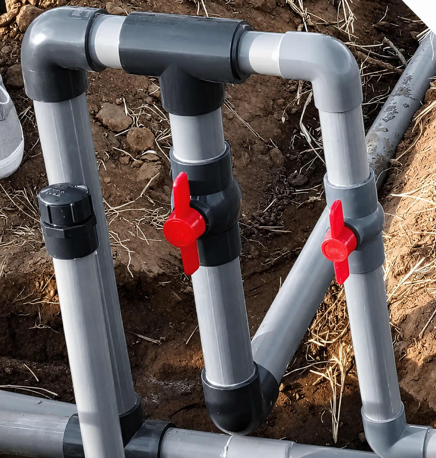
A pressure test tells you one thing: whether the section held. It does not tell you where it did not. On a new plastic installation this gap is expensive, because the section that just failed is typically anywhere from a few hundred metres to a kilometre of buried pipe, or a whole floor of first-fix pipework behind screed and plasterboard, and the difference between opening one metre of trench and opening two hundred is entirely a question of how well you can locate the point before the excavator starts.
This article is about that second step. We have written separately about why a falling gauge on plastic pipe is often creep rather than leakage, and that distinction is the prerequisite here — do not go looking for a leak point until you are satisfied the curve is genuinely a leak curve.
The awkward truth, stated up front: leak location on new plastic pipework is harder than on the metal systems most detection equipment was designed for, and several of the methods field crews reach for first are the ones that degrade most on plastic. We will be specific about where the published evidence supports a method, and equally specific about where we could not find a citable basis for a number that circulates widely in the trade.
Before deploying anything, read the test data you already have. The shape of the pressure decay carries diagnostic information that narrows the search, and it is free.
Notice what the published procedures have in common: they step the pressure down and then watch. Under BS EN 806-4:2010 Test Procedure A for plastic (visco-elastic) pipework, as set out in Northumbrian Water’s Guidance Note 3 (rev 4, 2019), the pipe is pressurised to 1.1 × maximum design pressure, maintained by pumping for 30 minutes, then reduced to one third of test pressure and held 90 minutes. Essex & Suffolk Water’s Guidance Note 3, implementing the BS EN 805 contraction method, reduces by 10–15% of System Test Pressure and observes for 30 minutes, extendable to 90 in case of doubt.
That step-down is not administrative. It is the mechanism that separates a leak from the pipe’s own visco-elastic behaviour, and the direction of the curve afterwards is the single most informative piece of evidence you will get for free. Under the EN 805 method an upward curve indicates a pass and a falling curve indicates a leak; PPI TN-46 (2021) Phase III says the same thing — a continuously falling rebound curve means the pipeline is leaking.
Caveat on all EN numbers in this article. We were not able to open BS EN 806-4:2010 or BS EN 805 themselves — both are paywalled at CEN/BSI. Every clause-level figure above is taken from UK water utility guidance documents that explicitly cite those standards by test procedure name. Treat the standards as governing and the numbers as secondary-sourced; buy the standard before you put clause-level figures into a specification or a test certificate.
| What the curve did | What that points toward | Sourced basis |
|---|---|---|
| Pressure fell steadily, and continued falling after the step-down with no rebound | Consistent with a real leak; proceed to location | PPI TN-46 (2021) Phase III: continuously falling rebound curve means the pipeline is leaking |
| Pressure fell but rebounded or went static after the step-down | Consistent with visco-elastic creep, not leakage | PPI TN-46 (2021) Section 1.0: self-limiting creep expansion is normal behaviour and is not an indication of a leak |
| Took far longer and far more water than expected to reach test pressure; response non-linear | Trapped air is a leading candidate before pipe or joints | PPI TN-46 (2021) Figure A-1: air content demonstrated at 0/1/3/5/7% on 1 km of 800 mm SDR 11 PE 100; PPI states response is increasingly non-linear with excessive entrained air |
| P90 came in at or below 70% of STP | Test failed — but from a leak or from excessive trapped air dissolving | PPI TN-46 (2021) Appendix A Phase I: pass if residual P90 > 70% of STP; at or below, failure may be either cause |
That last row is the one that sends crews digging in the wrong place. A failed rebound test is not proof of a leak. TN-46 states the failure may come from a leak or from excessive trapped air going into solution under pressure, and the two are not distinguishable from the pass/fail result alone.
Air is the most common reason a new plastic system fails a test with no leak to find, and PPI provides a quantified test to separate the two rather than leaving it to judgement.
TN-46’s Phase II air volume assessment works by bleeding water out in under 5 minutes to reduce pressure by 10–15%, measuring the bled volume ΔV, and comparing it against an allowable maximum:
ΔVmax = 1.2 · V · ΔP · {(1/Ew) + (D/(t · ER))}
where the 1.2 is the air allowance factor. If the measured ΔV exceeds ΔVmax, TN-46 states the test has failed and the cause must be corrected. The logic is straightforward: air is compressible, water is very nearly not, so an excess of removed volume for a given pressure drop is a direct measure of gas in the section. Running this before mobilising leak location equipment is the cheapest diagnostic step available on a new install.
You may have heard of the “double bump test” used for the same purpose. We looked for a standards or association basis with a numeric acceptance threshold and did not find one — the method appeared only in a ductile-iron manufacturer’s blog, with no quantified pass/fail criterion we could cite. TN-46’s Phase II is the verified substitute, and it is the one we would use.
If Phase II says the air content is out of bounds, the corrective work is upstream of any detection technology — refill and re-vent to the fill-rate and stabilisation conditions summarised in the conditions table below, rather than mobilising equipment. PPI warns that dissolved air can be eruptive, can cause a large surge pressure event, and can disguise a possible leak; the last of those is the one that wastes a week.
Before any sensor comes out of its case, the highest-yield technique on a new install is bisection — splitting the failed section and re-testing the halves. It requires no specialist equipment, produces an unambiguous result, and its effectiveness is a direct consequence of something PPI states plainly.
TN-46 Section 3.0 notes that PE pipelines longer than 3000 ft (about 915 m) may need to be tested in several sections, and that the longer the test section, the harder it is to locate a leak or to discriminate between a leak and other effects such as entrapped air dissolving into solution under pressure. Read that as a location statement, not just a testing statement: section length is the single variable that most determines whether you can find the point, and it is decided at planning stage, before anyone has a problem.
The practical consequence is a sequencing decision that costs nothing if made early and a great deal if made late. If a 900 m run is tested as one section and fails, you have 900 m of candidate. If the same run is tested in three sections as construction progresses, a failure implicates 300 m, and one bisection of that brings you to 150 m. TN-46 also constrains test pressure at any point in the section to not less than the design pressure and not more than 25% to 50% above the design pressure rating of any pipeline component — worth checking when you re-pressurise a sub-section, because the shorter section may have a different elevation profile and therefore a different pressure at its low point.
Our view, offered as experience rather than as a sourced standard requirement: on projects where the pipework is still open, bisection almost always beats instrumented detection on both time and certainty, and the reason crews skip it is that the isolation points were never installed. Specifying test-section valves or capped tees at planned intervals is a leak-location decision disguised as a fittings decision — worth reviewing against the tees, caps and valve bodies available in each jointing system while the layout is still on paper.
Performance Pipe’s Technical Note PP 802-TN states that leaks in newly constructed or newly modified piping systems typically occur at joints or connections, not in the pipe barrel, which is why post-failure investigation is directed at joints and connections first. On a new install this prior is strong and it should shape the search order: fusion joints, mechanical connections, transitions and terminations before mid-barrel. Transitions between materials deserve particular attention, since a plastic-to-metal changeover concentrates several failure modes at one point — our brass transition fittings and valves sit at exactly those junctions.
Several of the pre-test conditions in the table below — fusion joints cooled to ambient, mechanical connections fully tightened, the line restrained against movement — are worth re-reading as location hints rather than as compliance items. A joint that moved under test pressure because the line was unrestrained is both a leak and a clue about which joint to open first.
Acoustic correlation is the default leak-location technology in most water networks and it is genuinely effective — on metal. Anyone hiring acoustic detection for a new plastic install should understand the mechanism of the limitation rather than discovering it on site.
The core finding, from a comparative sensor study published in Sensors: acoustic methods are effective in metal pipes but perform substantially worse in plastic pipes because of substantial attenuation of leak sound signals. The field measurement behind it is more useful: a study of a buried high-performance polyethylene (HPPE) pipe measured attenuation of 1.6 dB/m at 150 Hz — roughly 32 dB of loss at a sensor 20 m from the leak, and about 48 dB at 30 m.
Two consequences follow. Sensor spacing on plastic has to be far tighter than on metal to keep signal above noise, which means more access points — and on a new buried install, access points are exactly what does not exist yet. And the frequency content sits low, which changes which sensor will see it at all.
Cross-correlation location places sensors at two access points either side of the suspected leak and derives position as s = LA + c · Δt, where c is the wave propagation speed and Δt the measured time delay. Location error therefore scales directly with error in the assumed wavespeed.
On the tested buried HPPE pipe, leak noise wave propagation speed was 356 m/s, with reported seasonal variation from 350 m/s to 420 m/s. Note that this range is strongly asymmetric about the measured value: relative to 356 m/s it runs about −1.7% at the bottom and about +18% at the top. That matters for how you read your own error, because the plausible error is almost entirely in one direction — a wavespeed assumed from a single measurement is far more likely to be too low than too high, which biases the derived position rather than merely blurring it. Taking the +18% end on a 100 m sensor separation, the derived position moves by metres — and metres, in a trench, is the whole cost question.
What we will not tell you: a pinpoint accuracy figure for acoustic correlators on plastic pipe in real field conditions. We looked. The only accuracy number we found in the literature — 0.1 m — is explicitly presented as an ideal theoretical/design figure under laboratory conditions, not a field-achievable specification. Claims that correlators pinpoint leaks “within a few inches” appeared only in vendor marketing copy and we could not verify them against any standard or peer-reviewed source. If a detection contractor quotes you an accuracy spec for plastic pipe, ask what conditions it was measured under and what wavespeed was assumed.
The published figures for leak noise frequency in plastic pipe do not agree with each other, and we are not going to pretend otherwise by picking one.
| Reported band | Conditions | Source |
|---|---|---|
| 10–150 Hz analysis band; hydrophone peak ~10 Hz, geophone peak ~16 Hz, accelerometer peak ~32 Hz | Buried HPPE field pipe | On the Acoustic Filtering of the Pipe and Sensor in a Buried Plastic Water Pipe (PMC) |
| Plastic pipeline 300–1000 Hz; metal pipeline 500–1500 Hz (half-power bandwidth) | Correlator design study — source-specific, contested by the above | Information Technology Journal, Leak Acoustic Signal Correlator for Water Pipelines |
| 1–2 mm circular leaks: ~80 Hz–20 kHz; 4–10 mm slits: predominantly 500 Hz–10 kHz | PVC pipe, leak-geometry dependent | Sensors (MDPI/PMC), Comparative Study of Leak Detection in PVC Water Pipes |
These are not reconcilable into a single industry constant, and we found no basis for stating one. What the disagreement itself tells you is the operationally useful point: frequency depends on pipe material, diameter, leak size and geometry, pressure and sensor type. A new-install leak at a fusion joint and a corrosion pinhole in an old main are not the same acoustic problem, and equipment tuned for one is not automatically right for the other.
The Sensors comparative study on PVC quantified two things usually treated as details. Sensor material: PVDF (polymer) gave the greatest sensitivity at 0.4 dB/(L/h) for 1 mm leaks, surface acoustic wave sensors 0.16 dB/(L/h) — about 60% less — and PZT ceramic lowest at 0.12 dB/(L/h). Standoff: sensitivity degraded at 0.55 [dB/(L/h)]/m, with about 9% error margin, moving sensors from 14 cm to 38 cm from the leak in the laboratory.
Note the scale on that second figure. That degradation was measured over a change in standoff of 24 centimetres. On a buried line where your nearest access point may be tens of metres from the leak, combined with the 1.6 dB/m attenuation figure above, the signal budget is the constraint — not the instrument’s processing.
Where acoustic methods are fighting the pipe material, tracer gas is largely indifferent to it, which is why it deserves more consideration on new plastic installs than it usually gets.
Forming gas — 5% hydrogen in 95% nitrogen — is non-flammable, non-toxic, odourless and tasteless. Per Pfeiffer Vacuum’s leak detection guidance, hydrogen’s low density causes it to rise to the surface where it is detected with a probe, which is precisely what makes it applicable to buried water pipes; the stated detection limit for forming gas 95/5 is 5 × 10⁻⁷ mbar·l/s. It is not only an industrial technique: Fränkische’s Pressure Test Guide, citing ZVSHK practice, lists the same 5% hydrogen mix as an accepted medium for locating leaks in drinking water installations.
The mechanism is the advantage. The gas escapes at the leak and migrates upward through soil to a surface probe; it does not have to propagate as a pressure wave along a highly attenuating plastic pipe wall, so the 1.6 dB/m problem simply does not apply. What it requires is that the section be emptied and filled with gas — operationally significant, and the reason it suits a section already implicated by bisection rather than a blind search over a kilometre.
We were not able to verify the EN 1779 classification of tracer gas leak detection methods or any quantified pinpointing accuracy for buried plastic pipe under that standard — the standard text was not accessible to us and we found no authoritative accuracy figure. So: strong physical basis, verified detection limit for the gas itself, no citable field-accuracy number from us.
There is a persistent temptation on new installs, particularly in building services, to test with compressed air because it avoids filling, draining and disposal. The distinction that matters is between a low-pressure impermeability test and a compressed-gas strength test, and between building pipework and buried pressure mains.
For drinking water installations inside buildings tested with compressed air or inert gas under ZVSHK practice as documented by Fränkische, the leak (impermeability) test pressure is 150 mbar with a manometer readable to 1 mbar, and the test time is at least 120 minutes for up to 100 litres of pipeline volume, increased by 20 minutes per additional 100 litres. The compressed-air strength test in the same practice is size-dependent: maximum 3 bar for nominal sizes up to and including 63 × 4.5 mm, and maximum 1 bar for sizes above 63 × 4.5 mm, each for a test period of 10 minutes.
Those pressures are low by design. Now the counterweight, from Performance Pipe PP 802-TN: pneumatic (compressed gas) leak testing of PE pressure piping systems is placed outside the scope of that note for safety reasons and referred to ASTM F2786, because failure during pneumatic testing releases both the piping stress energy and the compressed gas energy and can be explosive.
Both of those statements are correct within their own scope, and conflating them is how people get hurt. A 150 mbar impermeability check on small-bore building pipework is not the same activity as pressurising a buried PE main with compressed gas. Do not carry the former’s acceptability across to the latter.
Several published requirements are usually filed under “test planning” but are in substance leak-location requirements. They determine whether a leak, once present, can be found at all.
| Condition | Requirement as published | Why it governs location | Source |
|---|---|---|---|
| Weather and trench state | Schedule the hydro-test in dry weather so that leaks may be detected; testing in wet weather or in water-filled trenches is not recommended | Visual location of a buried leak is impossible in standing water; this is the single most-ignored constraint on new-install location | PPI TN-46 (2021) Section 4.0 |
| Instrumentation | At least two calibrated gauges cross-checking each other, typically one at each end of the section; calibration within the last year; readings recorded at minimum half-hour increments; gauge range to 150% of maximum allowable test pressure | Two gauges distinguish a real pressure loss from an instrument fault before you mobilise a search | PPI TN-46 (2021) Section 4.0 |
| Section length | Sections over 3000 ft (~915 m) may need to be split; longer sections impair discrimination between a leak and other effects | Section length sets the size of your search area, and it is fixed before the test | PPI TN-46 (2021) Section 3.0 |
| Air content | Fill and purge to less than 4% trapped air by volume; 3–24 h for thermal equilibrium and venting; fill velocity under 10 ft/min | Air produces failures with no leak to find, and PPI states it can disguise a possible leak | PPI TN-46 (2021) Section 3.0 and Appendix A |
| Restraint and cure | Fusion joints cooled to ambient; mechanical connections fully tightened; line restrained by backfill or sandbags; cast concrete thrust blocks cured in excess of 7 days | An unrestrained line creates the leak it then fails on, at a joint you would not otherwise suspect | PPI TN-46 (2021) Section 4.0; Performance Pipe PP 802-TN |
| Temperature (building services) | Temperature equalisation required where ambient-to-water difference exceeds 10 K, with 30 min waiting period after filling; gauge resolution 0.1 bar | A thermally unsettled system produces a decay curve you cannot read as leak or no-leak | Fränkische Pressure Test Guide, citing DIN EN 806-4 |
This is not a caveat at the end of a method. It is the constraint that shapes the method.
Performance Pipe PP 802-TN states: never approach or attempt to repair or stop leaks while the test section is pressurised; always depressurise the test section before making repairs. And the reason, in the same document: leakage at a joint may immediately precede catastrophic failure.
The practical implication for location work is that “walk the line under pressure and look for the wet patch” — which is how a great many new-install leaks are actually found — carries a real hazard at a joint that is in the process of failing. Depressurise before approaching a suspected point, and treat a visible weep at a joint as a warning, not as a convenient marker.
One further scoping point from the same note, worth putting in front of anyone who treats a passed test as a warranty: leak testing does not verify pressure rating or long-term performance. System design and the pressure ratings of the installed components are the sole determinants of system pressure rating and long-term performance. A section that passes has demonstrated that it does not leak today at test pressure. It has not demonstrated that it was correctly specified.
Leak location on a new install is iterative — test, isolate, re-test — and on PE that iteration is bounded in a way that catches crews out. Performance Pipe PP 802-TN caps total test duration at 8 hours when testing above system design pressure and up to 150% of system design pressure, including pressurising, initial expansion, time at test pressure and depressurising. If the test is not completed within that window, the note requires full depressurisation and at least 8 hours of relaxation before re-pressurising.
Three consecutive re-tests chasing a leak through a section is therefore not three hours of work — with the relaxation periods it can be most of two days. A crew that skips the relaxation is testing a pipe that has not returned to its baseline state, which corrupts the very curve they are trying to read. Plan the bisection sequence around this before mobilising, not after the first re-test.
Putting the above in order. This is our recommended sequence, assembled from the sourced requirements cited throughout; the ordering itself is our judgement, not a standard’s.
We manufacture and supply the pipe and fittings; we are not a leak-detection contractor, and it would be dishonest to imply we can specify your detection survey. IFANNova is a French brand, but the pipe is manufactured by Zhuji Fengfan Piping in Zhejiang, China — we do not claim French manufacture. Certifications listed are SKZ, CE, WRAS, DVGW, SGS, ISO 9001 and ISO 14001, with certificate numbers Coming soon (per our catalogue).
The constraint that matters most for anyone reading this article: our pressure pipe range tops out at Φ110 mm. We cannot supply DN150–DN400 transmission mains, and if your test section is a buried distribution main at those diameters, we are not your pipe supplier for it. Being direct about that is more useful to you than a brochure claim. The published outside diameters and wall thicknesses we do carry are set out in the HDPE pipe diameter chart and the wider pipe sizing charts, which is where to check a test section against our range before you specify it.
| System (per our catalogue) | Size range | Relevance to new-install leak location |
|---|---|---|
| HDPE PN16 | Φ20 × 2.3, Φ25 × 2.3, Φ32 × 3.0, Φ40 × 3.7, Φ50 × 4.6, Φ63 × 5.8, Φ75 × 6.8, Φ90 × 8.2, Φ110 × 10.0 mm | Buried service and branch lines. Two compression (weld-free) series available, 603 and 604 — mechanical connections that must be fully tightened before test per PP 802-TN |
| PPR PN20 | 1103 pipe in 20 × 2.8, 25 × 3.5 and 32 × 4.4 mm only, 4 m lengths | Building-services first fix. Socket (heat) fusion jointing. 1138 fittings series, 75 items in total |
| UPVC 806 PN16 | WP55 pipe Φ20 × 2.0, Φ25 × 2.0, Φ32 × 2.4, Φ40 × 3.0, Φ50 × 3.7, Φ63 × 4.7, Φ75 × 5.6, Φ90 × 6.7, Φ110 × 7.2 mm, 4 m lengths | Solvent-cemented systems; 1806 series comprises 203 items including ball valves and solvent cement |
| PEX | 2114 compression (S16/S20); 2121 press (16/18/20/25/26/32 mm). Diameters only — the catalogue publishes no wall thickness and no pressure class for these | Mechanical joints concealed in screed — the case where section isolation planning matters most. Ask us for wall and pressure class before you specify a test pressure against it |
| PVC 902 drainage | 902 pipe Φ32 × 1.6, Φ40 × 1.6, Φ50 × 1.8, Φ63 × 1.8, Φ75 × 1.8, Φ80 × 1.8, Φ90 × 1.8, Φ100 × 2.2, Φ110 × 2.2 mm; 1902 fittings Φ32–160 mm. Non-pressure | Non-pressure drainage only. Note the pipe stops at Φ110 — only the 1902 drainage fittings run to Φ160. None of the pressure-test procedures in this article apply to it |
| Brass 2405 | 1/4″ to 1″ | Transition and termination points — a common new-install leak location |
Two disclosures we would rather make ourselves. Our HDPE pipe is marked “GERMANY STANDARD DIN8077/8078” on the barrel. That designation is in fact the polypropylene standard; the PE equivalents are DIN 8074/8075. We report the marking as it appears and do not claim the pipe is manufactured to or conforms to DIN 8077/8078 — if your test documentation requires a stated pipe standard, raise this with us before you specify. Second, our PPR specification permits up to 10% recycled content, with the catalogue stating quality is not affected; the PPR is described as non-toxic and suitable for potable water, but where commissioning is tied to a potable-water approval, treat certificate numbers as Coming soon and ask us first.
On wall thicknesses: the table above gives every published size for HDPE, UPVC 806 and PVC 902 as its own row, not as a range with the middle left to your imagination — because on a pressure test the wall is what sets the hoop stress, and a specifier who has to interpolate is guessing at the number the test depends on. Two of our ranges genuinely do not carry one. Our PEX is catalogued by diameter only, with no wall and no pressure class; our brass fittings are sized by thread rather than by wall. Where the figure is missing we say it is missing and ask you to enquire — we will not back-calculate it from an SDR formula and present the result as product data.
In keeping with how we would want a supplier to write to us, the gaps:
Where a number is absent above, it is absent because we could not find a citable source for it, not because it does not matter.
If you are specifying pipework for a project where commissioning and leak testing are on the critical path, we would rather have the conversation about size limits, jointing method and isolation points before the order than after the test. Tell us the diameters, the pressure class, the jointing system you intend to use and where your test-section boundaries fall, and we will tell you plainly what we can supply against it and what we cannot.
Contact IFANNova for technical discussion or a quotation. Lead times, minimum order quantities and pricing are quoted against a specific enquiry — we do not publish indicative figures we cannot stand behind.
Plastic pipe pressure testing: how viscoelastic creep drops the gauge without a leak, the standard test methods, and how to tell relaxation from a real failure.
Organised by what the fitting does, not by catalogue order.
Drainage fittings sorted by function, not shape: trap seals (50 mm EN baseline, 75 mm for most UK appliances, 25 mm residual after test), branch vents within 750 mm…
