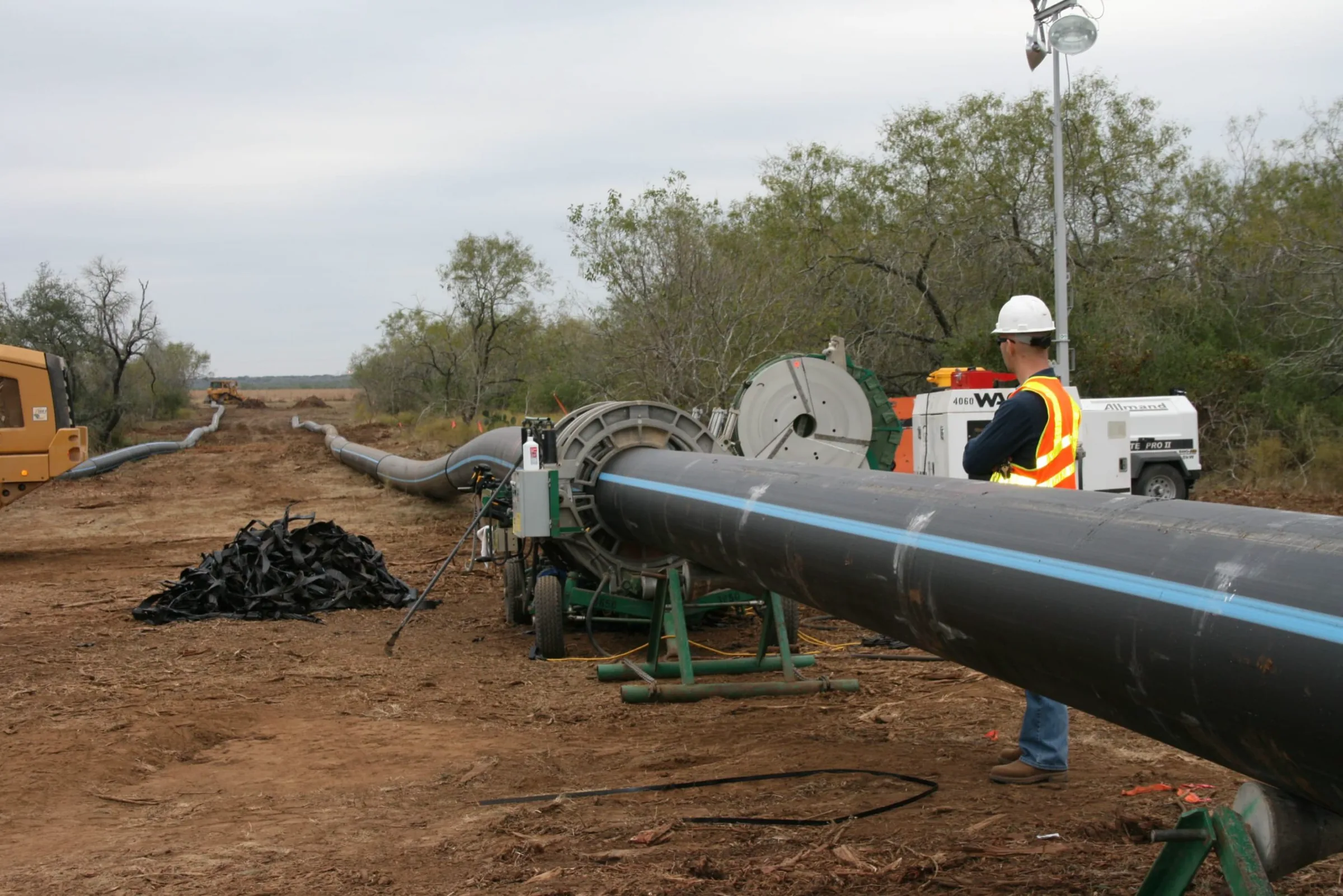
There are three ways to join HDPE pressure pipe in the field: butt fusion, electrofusion, and mechanical compression. Almost every comparison of the three ranks them by joint strength and stops there. That ranking is not useful, because it answers a question nobody on a live site is asking. All three methods produce joints that hold the pipe’s rated pressure when made correctly. The decision is not about the ceiling. It is about what each method demands from your crew, your generator, your trench width, your weather window and your inspection regime — and what happens to the joint when one of those demands is not met.
So this page compares the three methods on their process parameter windows and the tolerance each has for site reality. Every fusion method is a recipe with numbers in it: a temperature, a pressure, a soak time, a cooling time, a surface preparation depth. Those numbers are published, and we quote them below with the standard, edition and clause. What matters commercially is a different property of those numbers — how much room each method leaves you when the site cannot hold them. Butt fusion has a wide envelope but no forgiveness on cooling. Electrofusion automates the heat but concentrates almost all of its risk in a single manual step performed before the machine is even connected. Compression has no thermal parameters at all, which is exactly its advantage and exactly its limit.
Our position, stated before the evidence, because a comparison that hedges is worthless. Below roughly Φ110 — service connections, irrigation laterals, building-side branches, repairs — mechanical compression wins on total installed cost and on risk, and it wins by a wide margin, because the dominant failure mode of both fusion methods is workmanship and compression removes the workmanship variable almost entirely. Above that range, and on any buried transmission main, butt fusion and electrofusion win and compression is not a serious contender. That boundary is roughly where the standards themselves stop: ISO 14236:2000 caps its own scope at 160 mm.
Disclosure, up front. IFANNova supplies HDPE compression fittings — the 603 and 604 weld-free series, against our HDPE pipe and fitting range at Φ20–Φ110 (per our catalogue). We do not manufacture, sell, rent or service butt fusion machines or electrofusion control boxes, and we do not supply electrofusion fittings. We have a commercial interest in one of the three methods on this page. That is precisely why the sections on butt fusion and electrofusion below are built entirely from published standards and manufacturer manuals with the clause cited, rather than from our opinion — so you can check them without trusting us. And it is why the honest-limits section says plainly where compression is the wrong answer.
Butt fusion heats two squared pipe ends against a heater plate, withdraws the plate, and forces the melted faces together under pressure until they cool as one piece. There is no fitting. The joint is pipe-to-pipe.
The two most widely used parameter sets come from different continents and do not agree numerically — a fact that matters if you have a European consultant and an American contractor on the same job.
PPI TR-33 (2012), Generic Butt Fusion Joining Procedure for Field Joining of Polyethylene Pipe, Appendix A, specifies a heater surface temperature of 400–450 °F (204–232 °C). It applies to PE pipe per ASTM D2513 (fuel gas, MDPE/HDPE) and to PE potable water, sewer and industrial pipe per ASTM F714, D3035, AWWA C-901 and C-906. It explicitly excludes Dupont Aldyl A MDPE, Uponor Aldyl A MDPE and Phillips Driscopipe 7000/8000 HDPE.
The interfacial pressure range is 60–90 psi (4.14–6.21 bar), and TR-33 attaches a warning to it that is the single most misread line in the document. Verbatim, from Appendix A sections 4.0 and 5.0: “Interfacial pressure is used to determine fusion joining pressure settings for hydraulic butt fusion machines when joining specific pipe diameters and DR’s. Interfacial pressure in NOT the gauge pressure.” Fusion force is interfacial pressure multiplied by the pipe’s cross-sectional area; what the operator reads on the gauge depends on pipe diameter, DR and machine design, and drag must be added on top. A crew that dials 60 psi onto the gauge because the procedure says 60 psi has not followed the procedure.
DVS 2207-1 (September 2005, English translation), section 4.1.3, specifies a heated tool temperature of 200 to 220 °C for heated tool butt welding of PE-HD, and makes it wall-thickness dependent: “In principle the upper temperature limit is to be aspired for smaller wall thickness, the lower temperature limit for bigger ones… The upper temperature has to be chosen for PE 100 as well.”
Its pressure regime is expressed in different units and has a distinct third phase. Joining pressure is 0.15 ± 0.01 N/mm²; alignment (bead-up) pressure is 0.15 N/mm²; and during heat soak the pressure is deliberately reduced to near zero (≤ 0.01 N/mm²). These values are stated for an outside temperature of approximately 20 °C and moderate air flow.
The soak rule is arithmetic: heating-up time = 10 × wall thickness in mm, in seconds, at that near-zero soak pressure (Table 2, column 3).
| Parameter | PPI TR-33 (2012), Appendix A | DVS 2207-1 (Sept 2005) | What the difference means on site |
|---|---|---|---|
| Heater / tool temperature | 400–450 °F (204–232 °C), heater surface | 200–220 °C, upper end for thin wall and for PE 100 | Overlapping but not identical. DVS ties temperature to wall thickness and grade; TR-33 gives one band. |
| Joining pressure | 60–90 psi (4.14–6.21 bar) interfacial, explicitly not gauge | 0.15 ± 0.01 N/mm² | Different units, different reference. Neither is a gauge reading. Both require machine-specific conversion. |
| Pressure during heat soak | No pressure except brief seating contact | ≤ 0.01 N/mm² (near zero) | Both agree, and both treat violation as a defect. See the concave-face failure below. |
| Soak time | Governed by melt bead size (Table 2) | 10 × wall thickness (s), e.g. 19–26 mm wall → 190–260 s | TR-33 is observational, DVS is calculated. DVS is easier to audit from a log sheet. |
| Cooling under force | 30–90 s per inch of pipe diameter, or until bead is cool to touch; then avoid rough handling 30 more minutes | Per Table 2 by wall: 7–12 mm → 10–16 min; 26–37 mm → 32–45 min; 50–70 mm → 60–80 min | This is the schedule killer. See below. |
| Misalignment limit | Visually mitered joints must be cut out and re-fused | ≤ 0.1 × wall thickness on the pipe outside | DVS gives a measurable number; TR-33 gives a visual rejection rule. |
Butt fusion’s parameter windows are reasonably wide. Its cooling requirement is not, and it is the item that most often collides with a construction schedule, because the machine is occupied for the whole of it.
TR-33 (Appendix A, section 6.0 HOLD) requires holding fusion force for approximately 30–90 seconds per inch of pipe diameter, or until the melt bead surface is cool to the touch, then avoiding pulling, installation or rough handling for an additional 30 minutes — with more time possibly required where wall thickness exceeds 2 in.
DVS 2207-1 Table 2 puts the same constraint in wall-thickness terms, and the numbers climb steeply: a 4.5 mm wall cools in 6 minutes; a 12–19 mm wall in 16–24 minutes; a 26–37 mm wall in 32–45 minutes; a 50–70 mm wall in 60–80 minutes. Joining pressure must be maintained for the whole of that cooling time. On a heavy-wall large-diameter main, a single joint can occupy the machine and its crew for over an hour.
DVS does permit relief, but under conditions strict enough that they exclude most site work. Section 4.1.3 allows cooling time to be reduced by up to 50 % — releasing joining pressure and removing the part from the machine — only if all of the following hold: the welding is done under workshop conditions; removal and temporary storage cause only slight loads to the joint; and the component wall thickness is ≥ 15 mm. Full mechanical loading is permitted only after complete cooling per Table 2 column 5. In a trench, none of that applies.
Butt fusion has an unusual advantage: some of its worst failure modes announce themselves visually, at the moment they happen, to anyone who knows what to look at.
TR-33’s generic procedure is not universal. Appendix C states that the materials pre-qualified for it fall within a nominal melt index range of 0.05 to 0.25 g/10 min (190 °C/2.16 kg), or high load melt flow 6 to 17 g/10 min (190 °C/21.6 kg), and a nominal density range of 0.936 to 0.955 g/cc. PE materials outside that range may well be joinable, but they were not part of the study, and the pipe manufacturer must be consulted. If you are fusing a resin whose datasheet sits outside that envelope, the generic numbers are not automatically yours.
The validation envelope is worth knowing too. TR-33’s testing covered 2 in IPS DR11 and 8 in IPS DR11 in Sections I and II, and in Section III (PE 4710, per ASTM F2620-11e1) a range of pipe sizes from 6 in to 36 in and up to 4 in wall thickness. Encouragingly for process robustness, testing at deliberately extended parameters — heater face at 375 °F and 475 °F (191 °C and 246 °C) and interfacial pressures of 50 and 100 psi (3.45 and 6.90 bar) — still passed all tensile, quick burst, high speed tensile impact and 100 % ultrasonic inspection tests at the sizes tested.
Two standards notes. TR-33’s Appendix A itself states: “ASTM F2620 is a refined and expanded copy of this Appendix and should be used as the guide for further qualification.” ASTM F2620-20ae02, Standard Practice for Heat Fusion Joining of Polyethylene Pipe and Fittings, covers PE fuel gas pipe and PE potable water, sewer and industrial pipe, and specifies three procedures — socket fusion, butt fusion and saddle fusion — primarily intended for, but not limited to, field joining in pressure, low pressure and non-pressure applications; no pipe size range is stated in its scope. We quote TR-33’s numbers rather than F2620’s throughout this page because F2620’s body is paywalled and only its scope is publicly readable; attributing those figures to F2620 would be citing a document we have not read. Separately, ISO 21307 Plastics pipes and fittings — Butt fusion jointing procedures for polyethylene (PE) pipes and fittings also governs this ground; its 2009/2011 editions applied to gas and water distribution systems in PE 80 and PE 100 for wall thickness up to and including 70 mm, and the current edition is ISO 21307:2017. We could confirm only its scope and that limit — the standard is paywalled and the ISO catalogue page returned an access error to us, so we print no ISO 21307 numeric parameters at all.
Electrofusion uses a fitting with heating coils moulded into its bore. The pipe ends are prepared, inserted, clamped, and current is applied via a control unit that reads the fitting’s own barcode. The melt expands and is contained.
The containment mechanism is worth understanding because it explains the method’s characteristic failure. Georg Fischer’s electrofusion manual describes it: heating coils are separated by cold zones where no heat is generated; the expanding melt reaches these zones, cools, and blocks further melt escape — and it is that blockage which generates the melt pressure the fusion needs. The joint is pressurised by its own geometry.
Which means that if the pipe end is not inserted past the innermost heating wire — a short stab — the geometry is gone. GF states the consequence: “the melt generated during the fusion cycle will expand and flow over the end of the exposed pipe inside the fusion zone. Heating coil wires are carried by the uncontained melt flow, causing shorting and rapid overheating of the fusion zones.”
You will find articles quoting a fusion voltage (39.5 V, 40 V) and a fusion time in seconds for a given diameter as if these were standard values. They are not, and we will not print one. Fusion parameters are carried on the fitting’s own barcode per ISO 13950 and are set automatically by the fusion unit (fusion units themselves per ISO 12176-2). TEPPFA cites 40 V and 80 V only as examples of values you should check for equipment compatibility, not as figures to work to. The correct instruction to a crew is: read the barcode on the fitting in front of you. Any article that hands you a fixed number is handing you a number that belongs to a different fitting.
The same applies to cooling. There is no single generic electrofusion cooling time in minutes valid across diameters, and we could not find a standard that gives one. What is published is relative: GF’s rule of thumb is that “the time needed for the material to cool to the point that it has regained adequate strength for rough handling such as bending or backfilling is three times the clamping time listed on the fitting label.” GF defines three distinct cooling terms — CT (clamp time), TT (time before pressure test at 150 % of MOAP and tapping) and RH (rough handling) — which are not interchangeable. TEPPFA and DVS 2207-1 both defer to the fitting manufacturer’s stated cooling times. Anyone quoting you “electrofusion cools in X minutes” as a general figure is inventing it.
The thermal cycle is automated, so the residual risk migrates to the manual step. It migrates almost entirely.
Georg Fischer’s position is unambiguous: “Improper pipe preparation is overwhelmingly the leading cause of unsuccessful electrofusion joint attempts” and “The majority of failed fusions can be attributed to improper or inadequate pipe scraping.” The minimum removal GF specifies is 0.007 in (approximately 0.18 mm) of pipe surface — described memorably as “approximately the same as two sheets of ordinary paper”. Sandpaper, emery cloth, wood rasps, metal files and abrasives or grinders are never allowed and will result in failed fusions.
DVS 2207-1 section 5.3 states the same requirement in metric: the welding zone surface must be completely machined with a scraping tool removing approximately 0.2 mm of wall thickness. TEPPFA’s large-diameter guide gives a minimum chip/swarf removal of approximately 0.2 mm, with a size-dependent table: at d315 an estimated swarf thickness of 0.20–0.40 mm against an abrasion limit <0.40 mm; at d800 an estimated 0.40–0.60 mm against a limit <0.80 mm.
The reason a fraction of a millimetre carries this much weight: a scraped and an unscraped pipe look identical once the coupler is slid over them, and the oxidised skin that scraping removes will not fuse. Nothing downstream in the process detects it. The control box logs a perfect cycle.
The US Department of Energy published a forensic account: OE-3: 2017-04, Electrofusion Coupling Failures (July 2017). Three installed electrofusion couplings at the Pantex Plant failed after approximately four years in service on a Safety Class water supply line. The manufacturer’s evaluation found no alignment or stab-depth marks (an improperly centred coupling and a severe mis-stab, negating cold zone performance); scraping performed with a rasp that removed no material, or peeler removal of less than 0.003 in and less than 0.002 in against a manufacturer requirement of at least 0.007–0.010 in; dirt and mud in the fusion area; and joints fused in a bind, with hammer blows applied to the coupling. On a crush test per ASTM F1055 §9.4.2, the pipe immediately separated from the coupling. The report’s conclusion: “It was determined that all three couplings were not properly installed… The main reason was poor or improper pipe preparation.”
For reference, that acceptance criterion reads: per ASTM F1055 section 9.4.2, separation of the fitting from the pipe at the fusion interface constitutes a failure of the test; minor separation at the outer limits of the fusion heat source, up to 15 % of the fusion length, may be seen and does not constitute a failure; ductile failure in the pipe, fitting or wire insulation is acceptable as long as the bond interface remains intact.
Peer-reviewed work from the University of Sheffield reaches the same conclusion at industry scale. Tayefi, Beck and Tomlinson (2019), International Journal of Pressure Vessels and Piping 171:271–277, state: “Electrofusion failures within the UK water industry has been well documented with the three main causes being: poor scraping, misalignment (including problems associated with ovality) and contamination.” The paper notes all three are associated with on-site practice — workmanship, not material.
TEPPFA’s Good Practice Guide for the Electrofusion Jointing of Larger Diameter Polyethylene Pressure Pipes (section 6) lists six root causes, and the mechanism behind each is instructive: misaligned pipes create high stresses and moving wires, causing overheating and melt flow at the inner or outer cold zone, producing voids or deformation; a joint not centred or with insufficient insertion sends melt and wires flowing uncontrolled into the pipe gap; excessive toe-in, scratches or flattening matter because scratches not removed by scraping “can result in poor bonding… this can result in the formation of a leak path”, and flattened pipe cannot be re-rounded; insufficient peeling leaves oxidised surface that “will result in insufficient bonding and leakage may occur”; and insufficient cleaning or cross-contamination matters because “a contaminating layer prevents the pipe surface from bonding with the fitting” — caused by body oils, lubricants and trench contamination.
Contamination is quantified in the UK water industry specification the Sheffield paper worked to: a resistance-to-contamination short-term burst test applies talc contaminant to the pipe before assembly, then pressurises specimens at a constant 5 bar/min until failure. For electrofusion couplers, failure should not occur below the pipe’s nominal pressure rating × 2.5 (PN × 2.5); for electrofusion saddle fittings a minimum of 18 bar must be achieved. The specified contaminant is fine china talc with a particle size of 0.63 µm to 6.3 µm, on 110 mm SDR 17 PE100 test specimens. A contaminant measured in micrometres is enough to be worth a test standard. That is the sensitivity you are managing in a trench.
Two conditions have to be met before the barcode is even read.
Roundness. DVS 2207-1 section 5.3 limits ovality for electro-socket welding to 1.5 % of the outside diameter, maximum 3 mm, with re-rounding devices permitted, and requires that fitting and pipe be at the same temperature level before welding. TEPPFA requires pipe ovality (dmax − dmin) in the area of fitting positioning to be <3.0 mm unless the fitting manufacturer specifies otherwise, with re-rounding tools reducing ovality in the fusion zone below 3 mm. GF explains why: an excessive annular gap that melt expansion cannot close “will result in a lower fusion pressure inside the coupling and possibly a weakened joint strength”, with melt expulsion possible at the coupling end. GF notes 2 IPS and smaller tubing is usually flexible enough that the coupling and alignment clamps provide rounding, while at sizes equal to or larger than 3 in IPS re-rounding clamps may be needed on either side of the fitting.
Temperature and power. GF states its electrofusion fittings can be installed at ambient temperatures from −10 °F (−23 °C) to 120 °F (49 °C). TEPPFA states: “The application range for Electrofusion is usually −10 °C to +45 °C”, and requires equipment to cover the full intended range. TEPPFA also sets the allowable EF fitting storage range at 0 °C to +50 °C, away from UV and weather — a real constraint on a Gulf or Sahel site where a container in the sun exceeds it comfortably. Fittings conform to EN 12201-3 / EN 1555-3. On power delivery, TEPPFA specifies that extension cables shall not exceed 50 m, must be fully rolled out, and must have a cross section of at least 2.5 mm². A coiled undersized drum on a long run is a fusion parameter, whether or not anyone treats it as one.
DVS 2207-1 also covers heated tool socket welding, and it uses a different and higher tool temperature than butt welding: 250 to 270 °C, against 200–220 °C for butt. Socket welding can be performed manually up to 50 mm pipe diameter; from 63 mm a welding device is required because of the higher joining force. Example Table 5 values: d=32 mm SDR11 — heating 8 s, changeover 6 s, cooling 4 min fixed; d=110 mm SDR11 — heating 50 s, changeover 10 s, cooling 8 min fixed and 50 min total. If a crew uses one hot plate set to a single temperature for both butt and socket work, they are wrong for one of the two jobs.
A mechanical compression fitting seals by squeezing an elastomeric gasket and gripping the pipe as a nut is tightened. There is no melt, no heat, no cooling, no power, and no fusion record. It is the only one of the three methods that can be disassembled and remade.
The governing standard states its own limits with unusual clarity. ISO 14236:2000(E), clause 1 Scope, verbatim: “This International Standard specifies the required properties and test methods for mechanical fittings intended to join polyethylene pressure pipes of nominal outside diameters not greater than 160 mm, used in water supply systems conveying potable water and water for general purposes at temperatures up to and including 40 °C. The nominal pressure of the specified mechanical fittings corresponds at least to the PN of the water supply system for which they are designed and is usually of PN 6, PN 10 or PN 16.”
Two numbers in that sentence are the whole argument for where compression belongs: ≤160 mm and ≤40 °C.
ISO 14236 clause 4 classifies compression fittings two ways, and the second one determines whether your joint resists pull-out at all:
Pull-out resistance testing per ISO 3501 applies only to class 1 fittings. A purchase order that says “PE compression coupler, Φ63, PN16” and does not say class 1 has left the joint’s most consequential property to whoever fills the order. If the line has thrust to resist and no external restraint, that is the specification line that matters more than the pressure rating. End connection type is one of the six axes along which any fitting has to be specified — the wider selection logic, including the NPT-versus-BSP thread trap, is set out in our guide to the types of pipe fittings.
ISO 14236’s acceptance tests for metal fittings, by PE grade (clause 8.2, Tables 4 and 5; plastics fittings are covered separately in 8.3):
| Test | Method & conditions | PE 63 | PE 80 | PE 100 | Requirement |
|---|---|---|---|---|---|
| Leaktightness under internal pressure with bending | ISO 3503, 20 °C, ≥1 h, test pressure 1.8 × PN | 9.0 MPa test stress | 11.4 MPa | 14.4 MPa | No leakage during test |
| Resistance to pull-out | ISO 3501, 20 °C, ≥1 h, class 1 fittings only | 4.5 MPa longitudinal test stress | 5.7 MPa | 7.2 MPa | Withstand without pull-out |
The longitudinal stress figures are exactly half the circumferential ones — the standard’s own note adds that for diameters larger than 63 mm, special equipment such as hydraulic rams may be necessary to produce the required force or bending radius, which is itself a signal about where this fitting family is expected to live.
You will see it asserted that compression fittings derate with diameter — typically “16 bar to d63, then 12.5 bar to d110”. That is a product-range fact, not an industry rule, and stating it as a rule is wrong.
It is true of the NDS PN16 range (tested/approved to ISO 14236), whose specification reads “PN 16 bar from diameter 16 to diameter 63” and “PN 12.5 bar from diameter 75 to diameter 110” across a 16–110 mm range, with “Not for use in hot water applications.”
It is false of Georg Fischer’s iJOINT range, which states a maximum operating pressure of 16 bar for the complete range from d20 to d110 mm, with the complete range DVGW approved PN16, a temperature range of −10 °C to +45 °C, and suitability for PE 80, PE 100 and PEX-a pipe. Its materials are declared: body (and thrust ring d75–d110) UV stabilized polypropylene; nut UV stabilized blue PP; clamp ring polyacetal (POM); gasket food-safe coated NBR; reinforcement ring stainless steel AISI 430. Test standards cited include ISO 14236, DIN 8076-3, AS/NZS 4129, ISO 3501, ISO 3503, ISO 3458 and ISO 3459.
Two ISO 14236-referenced ranges, opposite derating behaviour. The practical instruction: get the pressure-versus-diameter statement from the specific range you are buying, in writing. Do not carry a number across brands.
On temperature derating specifically: we looked for an authoritative numeric derating curve for compression fittings as a function of temperature and did not find one in any source we could open. What is verifiable is absolute limits only — ISO 14236 scopes to ≤40 °C water, GF iJOINT states −10 °C to +45 °C, NDS states not for hot water. We will not print a derating curve we cannot source. Ask the manufacturer.
ISO 14236 caps its scope at ≤160 mm, and commercial ranges sit at or below that: GF iJOINT runs d20–d110 mm; Plasson UK’s mechanical compression couplers are listed up to d125 (repair coupler 7610 at 125 mm), with reducing couplers to 110 × 90. This supports the general conclusion that compression is a small-to-medium-diameter method, with butt fusion and electrofusion taking over above roughly this range. It is not a marketing boundary. It is where the standard stops.
| Demand | Butt fusion | Electrofusion | Compression |
|---|---|---|---|
| Capital equipment | Fusion machine sized to diameter, heater plate, facer, hydraulics | Control box, clamps/alignment fixtures, scraper tools, re-rounding clamps at larger sizes | Wrench. Nothing else. |
| Power on site | Generator for heater and hydraulics | Generator plus compliant cabling — TEPPFA: extension ≤50 m, fully unrolled, ≥2.5 mm² | None |
| Consumable cost per joint | None (no fitting) | An EF fitting per joint | A fitting per joint |
| Working temperature window | DVS parameters stated for ~20 °C outside temperature and moderate air flow | GF: −23 °C to 49 °C; TEPPFA: usually −10 °C to +45 °C. EF fitting storage 0 °C to +50 °C | Fitting-specific. GF iJOINT −10 °C to +45 °C; ISO 14236 scope ≤40 °C water |
| Trench space required | Largest — machine must fit around the pipe and be removable without disturbing it | Moderate — clamps and fixtures | Smallest — wrench swing only |
| Time the joint occupies the crew | Longest. TR-33: hold 30–90 s per inch of diameter plus 30 min no rough handling. DVS: up to 60–80 min cooling at 50–70 mm wall | Barcode-driven fusion time plus manufacturer cooling; GF rough-handling rule of thumb = 3 × clamp time on the label | Minutes. No cure, no cool. |
| Dominant failure mode | Pressure applied during heat soak (concave face); misalignment beyond 0.1 × wall; disturbing the joint before cooling completes | Inadequate scraping — named the leading cause by GF and confirmed by DOE OE-3: 2017-04 and Sheffield 2019 | Under-insertion, over/under-tightening, wrong class for the end load |
| Is the failure visible before backfill? | Partly yes — bead geometry and concave-face criteria are checkable by eye per TR-33 §5.0/§7.0 | Largely no — an unscraped pipe looks identical once the coupler is on, and the control box logs a normal cycle | Yes — it leaks on test, and it can be dismantled and remade |
| Joint record for QA | Operator log / machine data depending on machine | Control box data per joint (fitting parameters per ISO 13950, units per ISO 12176-2) | No electronic record. Torque and insertion are procedural. |
| Size range | Large diameters; TR-33 Section III validation up to 36 in and 4 in wall | Wide; TEPPFA’s large-diameter guide scopes above dn315 mm | ISO 14236 ≤160 mm; commercial ranges typically d20–d110/d125 |
| Reversible? | No — cut out and re-fuse | No — cut out, new fitting | Yes |
You are laying long runs of large-diameter pipe of the same size and SDR, you have the machine and the trained crew, and the programme can absorb the cooling hold. It is the only method with no fitting consumable, which at length is a real cost advantage. It also produces a joint you can partly assess by eye at the moment of making it — a genuine QA asset that electrofusion does not offer. It is the wrong choice in a confined excavation, on tie-ins to existing pipe that cannot be pulled into alignment, and on jobs where the machine’s occupancy time dominates the programme.
You are working in a confined space, tying into existing pipework, joining fittings, joining across pipe types where the fixture cannot align pipes end-to-end, or you need a per-joint electronic record for handover. It is the method of choice on repairs and connections precisely because the pipes do not have to be brought into a machine. It is the wrong choice when your crew’s scraping discipline is unverified, because the failure it produces is invisible, delayed and buried — the DOE case took four years to surface on a Safety Class line. If you use electrofusion, the scrape is the joint. Budget for peeler tools, not rasps, and audit the swarf.
You are at or below roughly Φ110, on water at or below 40 °C, and any of the following is true: you have no fusion machine and no trained fusion crew; the site has no reliable generator; the connection is a service, lateral, meter connection, irrigation branch or repair; the joint may need to be dismantled later; or your programme cannot absorb fusion cooling times. In those conditions compression is not the compromise choice. It is the correct one, because it removes the variable that both fusion methods have identified as their own dominant failure cause: on-site workmanship under uncontrolled conditions.
Specify it properly and it holds: ISO 14236 class 1 if end load must be resisted, the manufacturer’s own pressure-versus-diameter statement in writing, and a stated temperature limit. If the diameter and pressure class are still open, settle them first against the DN, NPS, SDR and PN sizing charts, then choose the joint.
The line is above ~160 mm; the fluid exceeds 40 °C (ISO 14236 scope) or the manufacturer’s stated limit; the joint will be buried and inaccessible under a road or structure where dismantling is impossible and a leak is catastrophic; the client’s specification demands fully fused monolithic construction; or the design relies on the joint resisting end load and you cannot confirm class 1. In those cases fuse it, and we will tell you so.
Stated plainly, because a comparison written by a supplier is only credible if the limits are as prominent as the pitch.
| Item | Status at IFANNova | Detail |
|---|---|---|
| HDPE compression fittings | We supply | 603 and 604 weld-free (compression) series (per our catalogue) |
| HDPE pipe | We supply | PN16, nine diameters with published walls: Φ20×2.3, 25×2.3, 32×3.0, 40×3.7, 50×4.6, 63×5.8, 75×6.8, 90×8.2, 110×10.0 mm. Pipe body is marked “GERMANY STANDARD DIN 8077/8078” (per our catalogue). We flag this ourselves: DIN 8077/8078 is a PP standard; the PE equivalents are DIN 8074/8075. We report the marking as printed and make no conformity claim from it. |
| Butt fusion machines | We do not supply | Not manufactured, not sold, not rented, not serviced by us |
| Electrofusion fittings | We do not supply | Not in our catalogue |
| Electrofusion control boxes | We do not supply | Not in our catalogue |
| Scraper / peeler tools, re-rounding clamps | We do not supply | Not in our catalogue |
| Fusion training or operator qualification | We do not offer | Go to the machine manufacturer or a recognised training body |
| HDPE pressure pipe above Φ110 | We cannot supply | Our pressure range stops at Φ110. For DN150–DN400 transmission mains we are not your supplier and will say so rather than quote. |
| PPR (1103 pipe / 1138 fittings) | We supply, but note the range | PN20; pipe in 20×2.8, 25×3.5 and 32×4.4 mm only (4 m). 1138 is a fitting series number, 75 items. Joined by heat fusion and electrofusion. Recycled content ≤10 % with quality unaffected (per our catalogue). |
| UPVC 806 / PVC 902 | We supply | UPVC 806 PN16, WP55 pipe Φ20×2.0 to Φ110×7.2 (4 m), 1806 fitting series of 203 items. PVC 902 drainage: pipe Φ32–110, 1902 fittings Φ32–160, non-pressure only. (Per our catalogue.) |
| Certificate numbers (SKZ / CE / WRAS / DVGW / SGS / ISO 9001 / 14001) | Coming soon | We hold the certifications; the individual certificate numbers are not yet published here |
| Pull-out / bending test reports on 603 and 604 against ISO 3501 / ISO 3503 | Coming soon | We will not state an end-load class for our series until we can hand you the report. Ask and we will tell you what exists. |
| Price, MOQ, lead time | Coming soon | Quoted per enquiry |
| Reference projects and installed tonnage | Coming soon | We do not print case studies we cannot evidence |
One further clarification we make on every page: IFANNova is a French brand. The pipe and fittings are manufactured by Zhuji Fengfan Piping in Zhuji, Zhejiang — a manufacturer with 30+ years, 1000+ employees, shipping to 118+ countries from a 120,000 m² site. The product is not made in France, and anyone telling you otherwise about our goods is wrong.
Standard practice on our technical pages. These are the numbers we went looking for and refused to invent:
For context on how reliable PE jointing is when done correctly: an independent study of the UK National Sewers and Water Mains Failure Database analysing 2005–2009 data concluded a failure rate of 8 failures per 100 km per year against a recorded 65,279 km of PE pipe in the UK, and analysis of the same database revealed PE to be the best performing material with regard to failure rates (Tayefi, Beck & Tomlinson 2019). The same paper notes that pipe systems face two fatigue types over a 50-year design life — diurnal demand fluctuations (≤4 bar) running between 3.7 × 10⁴ and 9.0 × 10⁴ cycles, and pump/valve operation fluctuations (>6 bar) — and cites research indicating PE will exceed its expected 50-year design life by another 50 years at operating temperatures between 10 and 25 °C. Whichever joint you choose, it is being asked to survive tens of thousands of pressure cycles. That is the standard the workmanship has to meet.
Which HDPE joint is strongest? The wrong question, and we decline to rank them numerically. All three hold rated pressure when correctly made. We deliberately do not print a percentage comparison of electrofusion versus butt fusion joint strength — that figure circulates widely but we could not confirm it in any primary source. Treat it as Coming soon pending one.
Can I mix methods on one project? Yes, and most projects do — butt fusion for straight runs, electrofusion for tie-ins and fittings, compression for services and repairs. What must not be mixed is parameter sets: DVS 2207-1’s 200–220 °C butt figure and its 250–270 °C socket figure are for different operations on the same site.
Do compression fittings need a pipe stiffener? That depends on the fitting design and the manufacturer’s instruction. ISO 14236 distinguishes type 1 (external grip only) from type 2 (internal and external grip or support), which bears directly on it. Ask the manufacturer of the specific range and get it in writing.
What temperature can compression fittings take? ISO 14236’s scope covers water up to and including 40 °C. Individual ranges state their own: GF iJOINT declares −10 °C to +45 °C; NDS PN16 states not for use in hot water applications. There is no universal derating curve we could source.
Why does the cleaning agent matter for fusion? DVS 2207-1 section 3.2.1 specifies a 100 % vaporizing solvent — for example 99 parts ethanol at 99.8 % purity with 1 part MEK for denaturation — and warns that “The use of ethyl alcohol could result in a reduction of quality because of the contained water.” Cleaning paper must be clean, unused, absorbent, non-fuzzy and non-coloured. Given that a talc contaminant of 0.63–6.3 µm is enough to warrant its own burst test, residue from the wrong solvent is not a trivial concern.
Can you supply fittings for a Φ250 main? No. Our HDPE pressure range stops at Φ110, and we will say so rather than quote something we cannot deliver.
Can you quote a price for 603/604? Pricing, MOQ and lead time: Coming soon — quoted per enquiry. Send the schedule and you will get a written answer.
Tell us the diameters, the pressure class, the fluid temperature, whether the joints are buried or accessible, whether end load is restrained externally, and how many joints of each type. Send the schedule and you will get a written answer against our real range — including a straight “that should be fused, and we don’t supply that” wherever it applies.
Cold joints cause most field butt fusion failures and ultrasonic inspection cannot detect them.
DVS 2207-1 tabulates socket welding only to OD 125 mm and permits hand-held work only to 50 mm; from 63 mm a machine is required.
A PP-R puncture can be repaired in place with a fusion pin, but only if the damage is a clean hole.
