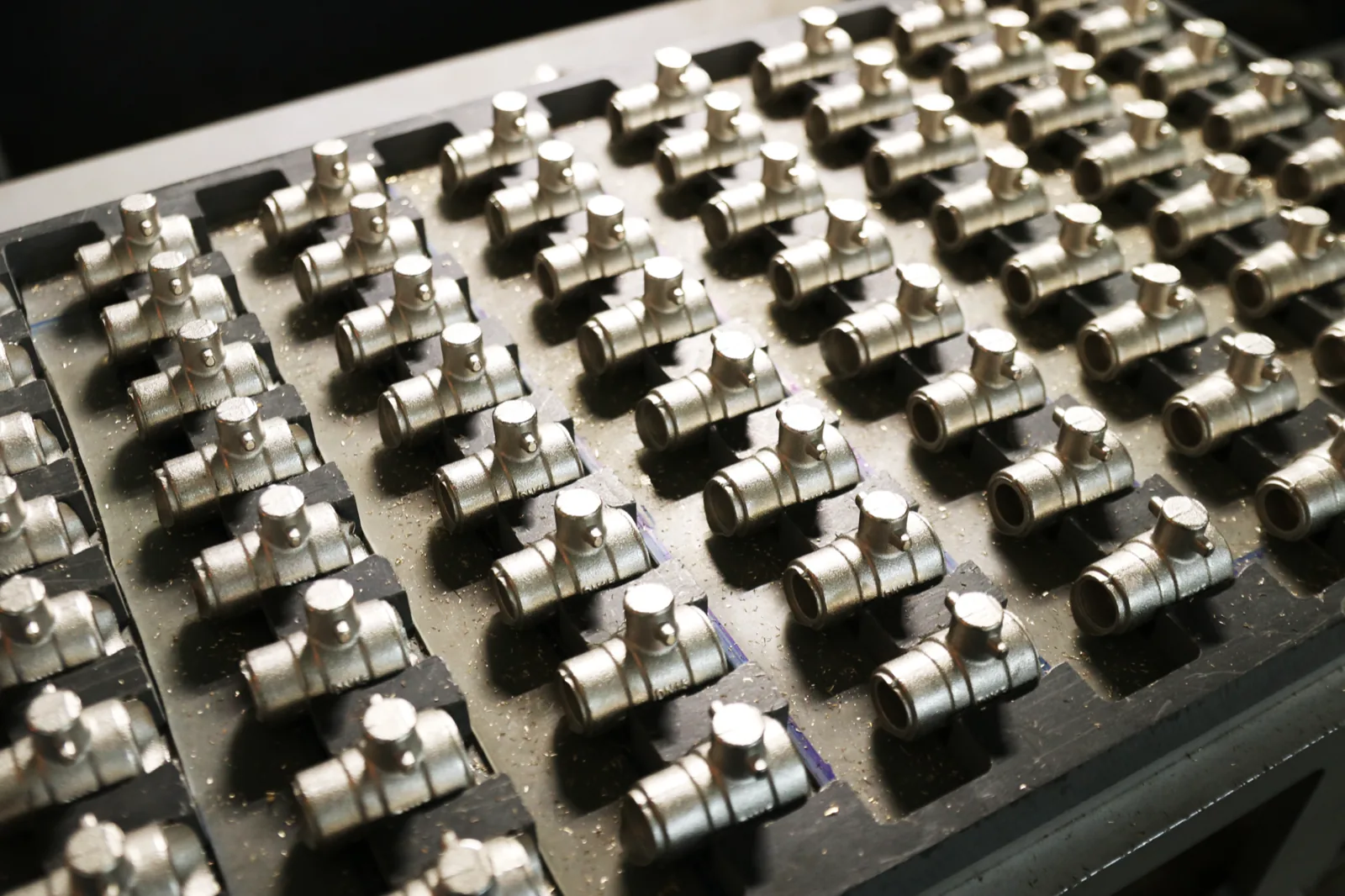
“Brass vs plastic fittings” sounds like a two-column decision. It almost never is. On the overwhelming majority of the schedules we quote, the answer is both — plastic through the distribution, brass at the points where the system meets something metal, something threaded, or something that has to be turned by hand. The real decision is not which material. It is where the boundary between them sits, and what you do at that boundary.
That reframing matters because the two failure modes people actually encounter are both boundary failures, not material failures. Galvanic corrosion happens where two dissimilar metals share an electrolyte. Thermal expansion mismatch happens where a material that moves a lot is rigidly restrained by one that does not. Neither is a property of brass. Neither is a property of plastic. Both are properties of the joint you built between them.
Our other pages cover the fitting families themselves — see types of pipe fittings for the functional taxonomy and thread standards, and thermal expansion in plastic chilled water piping for the anchor-and-guide maths. What follows is the part neither covers: the metal-to-plastic transition, and how to decide which side of it each item on your schedule belongs on.
Our position, stated up front rather than hedged at the end: use plastic by default and brass by exception, and let the exceptions be defined by mechanical duty rather than by habit.
Galvanic corrosion is often described loosely as “what happens when you mix metals.” That description is incomplete in a way that causes both over-engineering and under-engineering on the same project.
The mechanism requires three things simultaneously present:
Once those three are present the cell runs. How long they persist is a separate matter: duration is not a fourth condition, it governs how much accumulated metal loss you end up with, which is what turns a mechanism into a failure.
Remove any one of the three and the cell does not run at all. That is the entire engineering leverage available, and it is why the topic belongs in a fittings article: a plastic fitting placed between two dissimilar metals removes the second condition. It is a dielectric break by construction, not by accessory. That is a genuine, underappreciated argument in favour of plastic in mixed-metal systems, and it is one that does not depend on any performance claim about the plastic itself.
It also explains the mirror-image mistake. A brass fitting installed directly into a galvanised steel or ferrous component, with water on both sides, satisfies all three conditions. The plastic elsewhere in the system does nothing about it, because the cell is local. People sometimes assume a mostly-plastic system is immune to galvanic problems. It is immune only where the plastic actually interrupts the metal path.
We are not going to print a galvanic series table with potential values, and we are not going to give you a corrosion rate in mm/year for brass against steel in potable water. We looked for a citable primary source for comparative corrosion rates in this context and did not find one we could open and verify; numbers circulate without traceable test conditions, which invites specification against conditions nobody stated. If your project needs a quantified rate, that is a materials question for your consultant against your actual water chemistry.
The mechanism above is standard electrochemistry and is sufficient to make correct decisions without any number attached. You do not need a rate to know that direct brass-to-ferrous contact in a wet line is a choice requiring justification.
There is a second, distinct degradation mode that affects brass specifically and gets folded into “corrosion” in conversation. Dezincification is the selective leaching of zinc out of the brass alloy, leaving behind a porous copper-rich structure that retains the shape of the fitting while losing most of its strength. The characteristic field symptom is a fitting that looks intact, sometimes with a pinkish cast, and then fails suddenly under a pressure event or a spanner.
Two things make this operationally different from galvanic corrosion. It does not require a dissimilar metal in contact — it is a function of the alloy and the water, not of the couple. And it is not solved by adding a plastic isolation fitting, because there is no metal circuit to break.
The relevant procurement lever is alloy specification, and it is one most buyers never pull because they order “brass fittings” as a commodity. Where water is aggressive, dezincification resistance is a property you must specify, and the specification has to travel down to the material certificate, not just the purchase order line.
What we can state about our own brass, and what we cannot. Per our catalogue, our brass fittings are the 2405 series in 1/4″ to 1″, and our brass valve range covers ball, gate and check types in 1/2″ to 4″, manufactured in our own facility. We do not currently publish an alloy designation, a dezincification-resistance test result, or a certificate number against a specific brass standard for the 2405 series — those are Coming soon. We are deliberately not writing “to European standards” over that gap: a conformity phrase with no nameable standard behind it is the kind of claim this page exists to avoid. If dezincification resistance is a contract requirement on your project, ask us for it explicitly before ordering, and treat its absence from this page as the honest answer rather than an omission.
Plastics move substantially more than metals over the same temperature swing. That is well known, and for straight runs it is a solvable geometry problem — expansion legs, loops, anchors and guides, all covered in our expansion design article, which works through the calculation and the anchor loads.
What that article deliberately does not cover, and what this one is for, is the local consequence at a brass-insert fitting. This is where mismatch stops being a layout problem and becomes a joint problem.
Consider what a threaded brass insert in a plastic body actually is: a rigid metal ring encapsulated in a material with a much higher coefficient of expansion and a much lower stiffness. Every heating cycle the plastic tries to grow around a component that essentially does not; every cooling cycle it shrinks onto it. Stresses concentrate in the plastic immediately surrounding the insert — the region already thinned by the insert’s presence and already carrying the hoop stress of system pressure.
Three practical consequences follow, and they are the ones behind most enquiries about leaking transitions:
We are not publishing a torque figure for our transition fittings. For tapered pipe threads generally, torque and turns-past-hand-tight are not standardised quantities, and any figure in a specification is a house rule rather than a standard requirement. Values specific to our 2405 range and PPR/PEX transition parts are Coming soon. Until then, the correct site instruction is “to the manufacturer’s figure where one exists, otherwise conservatively and with a sealant appropriate to the thread form” — not a number invented on site.
These are the cases where we will tell you to buy metal, including when it costs us a plastic line item.
And these are the cases where specifying brass out of habit is the more expensive error.
| Consideration | Brass fittings | Plastic fittings | Which wins, and why |
|---|---|---|---|
| Galvanic corrosion risk | Participates in the cell when coupled to a dissimilar metal in a wet line | Non-conductive; breaks the metal circuit by construction | Plastic — this is a structural advantage, not a marketing claim |
| Dezincification | Alloy-dependent; needs explicit specification in aggressive water | Not applicable | Plastic where water chemistry is aggressive or unknown |
| Thermal movement of the component itself | Low; effectively dimensionally stable relative to the plastic around it | High; must be accommodated by layout | Brass in isolation — but the mismatch at the junction is the real issue |
| Repeated make-and-break threading | Tolerates service cycles well | Degrades with repeated disassembly | Brass at every serviceable connection |
| Handle torque and mechanical abuse | Designed for it | Not the right duty | Brass — valves, exposed positions, plant rooms |
| Over-tightening tolerance | Forgiving | Unforgiving, especially at brass-insert transitions | Brass where installation quality cannot be supervised |
| Weight in handling | Heaviest of the three referenced materials | UPVC approx. 1/6 of brass, 1/5 of steel (per our catalogue) | Plastic where site labour or lifting is constrained |
| Buried / inaccessible service | Introduces an uninspectable corrosion site | No electrochemical mechanism to monitor | Plastic |
| Size envelope we can actually supply | 2405 series 1/4″–1″; valves 1/2″–4″ (per our catalogue) | PPR 20/25/32 mm; UPVC & HDPE to Φ110; PVC 902 drainage pipe Φ32–110 with 1902 fittings to Φ160, non-pressure only (per our catalogue) | Neither above these envelopes — we say so rather than quote |
Most projects will mix. These are the rules we would apply, marked honestly as engineering practice and our own commercial experience rather than as standard requirements.
| Series (per our catalogue) | Material | Size envelope | Role at the brass/plastic boundary |
|---|---|---|---|
| 2405 | Brass fittings | 1/4″–1″ | The metal side: threaded connections, service points, interfaces to equipment |
| Brass ball / gate / check valves | Brass | 1/2″–4″ | Isolation and control — hand torque duty, always metal |
| 1138 (75 items) | PPR fittings, PN20 | Matched to 20 / 25 / 32 mm pipe only | Plastic distribution; brass-insert types form the transition |
| 1806 (203 items) | UPVC 806 fittings, PN16, incl. ball valves and solvent cement | Matched to Φ20 × 2.0 – Φ110 × 7.2 pipe | Plastic distribution; solvent-cement joints, no thread stress in the run |
| 603 / 604 | HDPE compression fittings, PN16 | Matched to Φ20 × 2.3 – Φ110 × 10 pipe | Mechanical joints, no fusion equipment required on site |
| 2114 / 2121 | PEX (sliding-sleeve / press) | 2114: S16, S20 · 2121: 16, 18, 20, 25, 26, 32 mm | Plastic distribution with metal-assisted joints |
| 902 / 1902 | PVC drainage | 902 pipe Φ32–110; 1902 fittings Φ32–160 — non-pressure drainage only | No brass interface applicable |
Our HDPE pipe carries the marking “GERMANY STANDARD DIN8077/8078” printed on the pipe body (per our catalogue). We reproduce that marking as it appears rather than as a conformity statement, because DIN 8077/8078 are the polypropylene standards — 8077 for dimensions, 8078 for general quality requirements and testing; the PE equivalents are DIN 8074/8075. We are not going to write “conforms to” over a marking we have not reconciled, and you should treat that discrepancy as something to raise with us in writing if the marking matters to your approval route.
A short and deliberate list, because a comparison article that admits nothing is not a comparison article:
One more point of honesty, since the brand invites the question: IFANNova is a French brand. The products are manufactured by Zhuji Fengfan Piping in Zhuji, Zhejiang — 30+ years, 1000+ employees, 120,000 m², shipping to 118+ countries (per our catalogue). They are not made in France, and we would rather you read that here than infer something else from the name.
Plastic through the distribution. Brass where a human turns it, where it will be unbolted for service, and where you meet metal you did not specify. Plastic wherever the run is buried, embedded or otherwise beyond inspection. Brass wherever installation quality cannot be supervised and an over-tightened joint is likely.
And at every point where the two meet: a deliberate, drawn, single transition — never an improvised one, never doubling as an anchor, and never with a thread designation that was assumed rather than specified.
If your schedule crosses that boundary more than a handful of times, send it to us and we will mark up which lines we can supply within our stated envelopes and which we cannot. We do not quote items we cannot manufacture, and we would rather lose the line than lose the project.
Send us your fittings schedule for a line-by-line supply check
At 45 °C a pipe loses pressure capacity, stiffness and surface integrity — three separate deratings governed by three different documents.
The pressure side of SDR is well covered elsewhere.
Same design stress, same 16 bar, different rounding convention.
