Our chilled water piping guide covers what comes before this: material choice, branch sizing, insulation and vapour barrier for a cold surface, and the product standards a submittal is checked against. None of that is repeated here. This article assumes HDPE is chosen. The next questions are almost entirely numerical: what pressure the pipe holds at condenser water temperature, how much a buried line deflects under a campus road, what pulls a buried joint apart, and what must be written into the trench specification.
One clarification first, because specifications conflate them. Condenser water is the pressurised loop between a water-cooled chiller’s condenser and the cooling tower. Condensate is water dripping off a coil into a drain pan — gravity drainage, a different problem. This article covers both pressure services. Where a project means condensate drainage, the governing practice is ASTM D2321 (gravity-flow thermoplastic pipe), not ASTM D2774 (thermoplastic pressure piping) (PPI Handbook of PE Pipe, Chapter 7, Nov 2025 revision, p.7-1). We could not locate a standards-body document specifying HDPE for HVAC condensate drainage. If a project needs that citation, treat it as Coming soon.
This calculation is usually skipped in one of two wrong directions: engineers assume plastic derates badly with heat and oversize, or assume it does not derate and undersize. The truth is favourable to HVAC, and worth knowing precisely.
The governing relation for HDPE in water service, in the ASTM F714 Appendix X5 form, is PR = 2 × (HDS)(FT)(FE) / (DR − 1). PR is pressure rating in psi; HDS is hydrostatic design stress at 73 °F (23 °C) in psi; FT is the temperature design factor; FE is the environmental design factor; DR is the dimension ratio, average outside diameter divided by minimum wall thickness (Chevron Phillips / Performance Pipe Technical Note PP 816-TN, Aug 2007, Eq. 1 p.4). PPI states the same relation generically as PR = 2 (HDB) × (design factor) / (SDR − 1). It defines PR as the estimated maximum pressure the medium can exert continuously with a high degree of certainty that failure will not occur (PPI TR-4/2018, p.11). HDS is the HDB after the design factor is applied.
| Service temperature | FT | Relevance to HVAC |
|---|---|---|
| ≤80 °F (≤26.7 °C) | 1.00 | All chilled water; cool-weather condenser water |
| 90 °F (32.2 °C) | 0.90 | Condenser water in mild ambient |
| 100 °F (37.8 °C) | 0.78 | Above most condenser water returns |
| 110 °F (43.3 °C) | 0.75 | — |
| 120 °F (48.9 °C) | 0.63 | — |
| 130 °F (54.4 °C) | 0.60 | — |
| 140 °F (60 °C) | 0.50 | Maximum temperature for pressure service |
Source: PP 816-TN, Table 3, p.5. The document permits straight-line interpolation between values; the 73 °F rating is good to 80 °F with no derating. Maximum temperature for non-pressure service is 180 °F (82.2 °C).
Now apply it. Chilled water design temperatures are 42–45 °F (5.6–7.2 °C) supply and 52–60 °F (11.1–15.6 °C) return (UFC 3-430-09, Table 2-1). The Fahrenheit values are the ones the source publishes; the metric equivalents are conversions, not separately specified design values, so quote the °F figures when you cite UFC. These are US federal design criteria, not universal values — European practice commonly works to a different band, and the two must not be mixed within one calculation. The same table gives condenser water as 85 °F supply and 105 °F return; the derating below is therefore worked at 95 °F, a figure inside that published band rather than at its return-side limit. The whole chilled water band sits in the no-derate zone — FT = 1.00, full rating, no calculation. Only condenser water return approaches the shoulder. At 95 °F, interpolating between 0.90 and 0.78 gives FT = 0.84, so for DR11 PE4710 (HDS = 1000 psi, PP 816-TN Table 2 p.4):
PR = 2 × 1000 × 0.84 × 1.0 / (11 − 1) = 168 psi, against 200 psi at ≤80 °F (PP 816-TN Table 5 p.6).
A 16% reduction at 95 °F. That is the headline: HVAC water services never approach the part of the curve where HDPE loses meaningful capacity. A designer applying a “plastic halves when warm” heuristic derates against a 140 °F condition a condenser loop will never see.
FE is easier. It equals 1.0 for potable and process water, brine, wastewater and — the relevant one — glycol/anti-freeze solutions. FE = 0.5 applies to solvating or permeating chemicals: hydrocarbons at ≥2% concentration, crude oil, fuel oil, gasoline, diesel, kerosene (PP 816-TN, Table 4, p.5). A glycol-inhibited loop carries no environmental derating. Only the pipe’s external environment triggers 0.5 — a contaminated-soil question, addressed later.
| DR | PE4710 at 80 °F (psi) | PE3608 at 80 °F (psi) | PE4710 at 95 °F, FT = 0.84 |
|---|---|---|---|
| 7.3 | 315 | 255 | 266.7 |
| 9 | 255 | 200 | 210.0 |
| 11 | 200 | 160 | 168.0 |
| 13.5 | 160 | 130 | 134.4 |
| 17 | 125 | 100 | 105.0 |
| 21 | 100 | 80 | 84.0 |
| 26 | 80 | 65 | 67.2 |
| 32.5 | 65 | 50 | 53.3 |
The 80 °F columns are PP 816-TN Table 5, p.6. The right-hand column is our own arithmetic, not a tabulated figure, and it should be labelled as such in a submittal. Every value in it is PR = 2 × 1000 × 0.84 × 1.0 / (DR − 1) — the same equation used above, with HDS = 1000 psi for PE4710 and FT = 0.84 from the source’s interpolation rule. Recompute any row directly from that expression: DR 9 gives 1680/8 = 210.0, DR 32.5 gives 1680/31.5 = 53.3. Note that this is not the same as multiplying the tabulated 80 °F rating by 0.84, because the tabulated ratings are themselves rounded; the two methods differ by up to about 2 psi, and we quote the equation result throughout.
The 1000 psi in that equation is not a measured strength. It is an extrapolation with a known way of being wrong — which matters more below grade than above.
Long-term hydrostatic strength is the stress that, applied continuously, causes failure at 100,000 hours (about 11.4 years); the HDB is that value categorised per ASTM D2837 (PPI TR-4/2018, pp.9-10). PE4710 is listed at HDB = 1600 psi at 73 °F and 1000 psi at 140 °F (PPI TR-4/2018, pp.29-30).
The mechanism is the ductile-to-brittle knee. Polyolefins may shift from ductile to brittle “slit” failure. That decreases long-term strength because the regression slope changes — the extrapolated straight line stops being straight. Higher temperatures shorten both time to failure and time to that transition, following an Arrhenius relationship. Ductile failure shows visible deformation (stretching, necking) at the break; brittle failure shows none (PPI TN-7/2005, Section IV.B pp.6-7; definitions from PPI TR-4/2018 p.9).
This matters differently underground. Brittle slit failure is slow crack growth, and slow crack growth starts at a stress concentration: a rock bearing on the wall, a gouge from dragging pipe into the trench, an unsupported span over a boulder. Every embedment clause later in this article exists to prevent the point loads that seed this mechanism.
One rule makes the rating system trustworthy: ASTM D2837 assumes linear extrapolation, and for polyethylene a validation procedure confirms it. Materials showing a knee in the 73 °F curve before 100,000 hours do not validate and are not given an HDB rating at all (PPI TN-7/2005, Table 1 Note 1, p.5; PPI TR-4/2018, p.12).
EU projects specify PE100; US projects specify PE4710. A bid comparison treating them as equivalent compares unlike things. The two systems differ structurally — ASTM D2837 classifies by HDB in psi, assumes linearity with validation required for PE, extrapolates at 73 °F to 100,000 hours, and uses the mean LTHS; ISO 9080 classifies by MRS in MPa, assumes no linearity, extrapolates at 20 °C to 50 years, and uses the 97.5% lower prediction limit (PPI TN-7/2005, Table 1, p.5). PE100 denotes MRS = 10 MPa.
The consequence, from the manufacturer’s note: the only requirement to be designated PE100 is an MRS of 10 MPa. The designation covers no other important pipe properties such as stress crack resistance. PE4710 additionally requires ASTM D3350 cell class 445474C, a minimum PENT slow crack growth time of 500 hours per ASTM F1473, tighter data scatter, and validation of curve linearity for 50 years (PP 816-TN, footnote 3 p.3 and pp.2-3).
Check that stress crack requirement when buried. ASTM D3350’s fifth digit is slow crack growth resistance by PENT (80 °C, 2.4 MPa notched). Class 6 is 100 hours; class 7, added in 2005, is 500 hours. PE4710 requires class 7; PE3608 is cell class 345464C, class 6 (PP 816-TN, Table 1 p.2). Since a rock in the backfill initiates slow crack growth, on a direct-buried line the PENT class is more informative than the pressure class. Our engineering opinion, not a sourced requirement: where you cannot control embedment quality, specify by cell class, not pressure rating alone.
AWWA M55 defines a “Design Window” inside which buried PE pressure pipe needs no deflection or buckling calculation:
Source: PPI Handbook of PE Pipe, 2nd ed., Chapter 6, Table 3-1 and bullet list, p.193. A manufacturer restatement adds the conditions: DR 21 or lower PE3608/PE4710, ground water at or below surface grade, installation per ASTM D2774, and E′ of at least 1000 psi at ≥85% Standard Proctor. Met, deflection stays within guidelines and the safety factor against constrained buckling exceeds 2 (WL Plastics WL113, Rev Dec 2024, pp.2-3).
PPI states a separate general rule for vehicular load: minimum one pipe diameter or 18 in (457 mm) beneath the road surface, whichever is greater, below which “Shallow Cover Vehicular Loading” calculations are required. State highway departments often require 2.5 to 5 ft (0.76–1.52 m) (PPI Chapter 6, pp.197-198). The two figures differ: 18 in general rule versus 3 ft in the Design Window. On a campus main crossing a service road, use the Design Window figure and check the local highway requirement on top. 18 in is the physics floor, not the specification.
PPI defines a “Basic Installation” usable when all of the following hold: nominal diameter ≤24 in (610 mm); DR ≤21; cover ≤10 ft (3.05 m); natural groundwater below the pipe; no live load nor surcharge load; foundation not expansive clay, collapsing soil or landfill; and maximum particle size per the embedment table. Then the pipe may be laid directly on the trench bottom, backfill may be excavated soil, and it need not be compacted. Basic Installation assumes E′ = 200 psi (1.38 MPa) at the pipe sides (PPI Chapter 7, Nov 2025, p.7-6).
Read the fifth condition carefully. “No live load” excludes any road, car park or plant access route. A campus lateral through landscaping often qualifies; the same lateral crossing a delivery road does not.
| Nominal pipe OD | Minimum trench width | Clearance between parallel pipes |
|---|---|---|
| Under 3 in | 12 in (305 mm) | 4 in (102 mm) |
| 3 in to 24 in | Pipe OD + 12 in (OD + 305 mm) | 6 in (152 mm) |
Source: PPI Chapter 7 (Nov 2025), Table 3, p.7-7; trenches must be wider where boxes or shoring are used. For a supply-and-return pair sharing a trench, give the excavation subcontractor the 6 in clearance plus two ODs plus the width allowance — usually wider than first priced.
Deflection is the buried failure mode nobody sees until a CCTV survey. The governing relation is the Spangler Modified Iowa formula:
ΔX/DM = KBED (LDL·PE + PL) / [ (2E/3)·(1/(DR−1))³ + 0.061·FS·E′ ]
ΔX is horizontal deflection (in); DM mean diameter (in); KBED the bedding factor, typically 0.1; LDL the deflection lag factor; PE and PL vertical soil pressures from earth and live load (psf); E the apparent modulus of the pipe material (psi); E′ the modulus of soil reaction (psi); FS the soil support factor. Percentage deflection is 100 × ΔX/DM (PPI Chapter 6, Eq. 3-10 and symbol list, pp.211-212). Watch the units: pressures are psf, moduli psi, and the /144 converts the psf pressure terms to psi so they match the moduli.
Earth load uses the prism load, PE = w · H: w is soil unit weight (pcf), H cover to the crown (ft). Absent site data, 120 pcf (1,922 kg/m³) is the common dry assumption; saturated weight applies below the water table. Ignoring arching and using the prism load is conservative for PE and may be safely used in virtually all designs (PPI Chapter 6, Eq. 3-1, p.196).
| Soil type | Dumped | Slight, <85% | Moderate, 85–95% | High, >95% |
|---|---|---|---|---|
| Fine-grained, LL<50, <25% coarse | 50 | 200 | 400 | 1000 |
| Fine-grained, LL<50, >25% coarse; GM, GC, SM, SC with >12% fines | 100 | 400 | 1000 | 2000 |
| Coarse-grained, little or no fines (GW, GP, SW, SP) | 200 | 1000 | 2000 | 3000 |
| Crushed rock | 1000 | 3000 | 3000 | 3000 |
| Fine-grained, LL>50 (CH, MH) | No data — consult a soils engineer, otherwise use E′ = 0 | |||
Values in psi. Source: PPI Chapter 6, Table 3-7 “Values of E′ for Pipe Embedment (Howard)”, p.214; valid for fills under 50 ft (15 m), no safety factor included. 1 psi = 6.9 kPa.
The span of that table is the point. Dumped fine-grained backfill (E′ = 50) to compacted crushed rock (E′ = 3000) is a factor of sixty. The pipe did not change. The specification clause that did or did not get enforced on site changed the answer by more than any DR selection can.
Two more inputs. HDPE’s apparent modulus falls with load duration at 73 °F: 110,000 psi short-term, 57,500 at 10 hours, 43,700 at 1,000 hours, 38,000 at 1 year, and 28,200 at 50 years — about a quarter of short-term. Using the 50-year modulus for earth load on low-DR pipe is conservative; for vehicle loads the lag factor is 1 (PPI Chapter 6, Table 2-6, p.212). Spangler recommended a lag factor of 1.25–1.5 for post-installation settlement, Howard showed it varies with embedment, and many plastic pipe designers use 1.0 with the prism load (PPI Chapter 6, p.216).
8 in IPS (OD 8.625 in), PE4710, H = 5 ft, w = 120 pcf, no live load, KBED = 0.1, LDL = 1.0, FS = 1.0, E = 28,200 psi. PE = 600 psf. Results are our arithmetic using PPI’s equation and input values:
| Embedment condition | E′ (psi) | DR 11 | DR 17 |
|---|---|---|---|
| Coarse-grained, moderate compaction | 2000 | 0.30% | 0.33% |
| Same, E′ reduced 25% for field variability | 1500 | 0.38% | 0.43% |
| Fine-grained, moderate compaction | 400 | 0.96% | 1.44% |
| Basic Installation assumption | 200 | 1.34% | 2.48% |
| Same, E′ reduced 25% | 150 | 1.49% | 3.03% |
Three things follow. At DR 11 with decent embedment, deflection is a non-issue. The DR 11 versus DR 17 difference is negligible in good soil (0.30% vs 0.33%) and only matters in poor soil (1.34% vs 2.48%) — wall thickness buys little deflection resistance; soil buys nearly all of it. At DR 11 the pipe stiffness term is about 19 against a soil term of 122 at E′ = 2000. Thicker wall is the right answer specifically where you cannot control backfill.
The 25% reduction rows are required, not extra conservatism. Deflection varies along a line and fits a Normal Distribution, so for anticipated maximum deflection the designer should either reduce the Table 3-7 E′ by 25% or add the tabulated accuracy correction: ±2% for dumped and slight compaction, ±1% moderate, ±0.5% high (PPI Chapter 6, p.213 and Table 3-7).
A standard H20 truck weighs 40,000 lb (18,144 kg) — 8,000 lb front axle, 32,000 lb rear. The HS20 is a tractor-trailer with the same axle loadings but two rear axles. Maximum wheel load is 40% of total truck weight, i.e. 16,000 lb. Paved-road impact factors by cover: 1.35 at 1 ft, 1.30 at 2 ft, 1.25 at 3 ft, 1.20 at 4 ft, 1.10 at 6 ft. For unpaved roads, impact factors of 2.0 or higher may occur (PPI Chapter 6, pp.198-199).
Live load uses Boussinesq: PL = 3 If Ww H³ / (π r⁵), with r = √(H² + X²) and X the horizontal offset; pavement effects neglected (PPI Chapter 6, Eq. 2-4/2-5).
Our arithmetic for a 16,000 lb wheel directly overhead on pavement: at 2 ft cover PL ≈ 4,966 psf; at 3 ft ≈ 2,122 psf; at 4 ft ≈ 1,146 psf. Earth load at those depths is only 240, 360 and 480 psf. At shallow cover the truck is an order of magnitude more load than the soil above the pipe. That is why the Design Window raises H20 minimum cover to 3 ft — and why an unpaved haul route across a line designed for finished pavement deserves attention.
Offset helps quickly. At 3 ft cover with the wheel 2 ft to the side, PL falls to about 846 psf; at 3 ft offset, about 375 psf (our arithmetic). Routing the main a few feet outside the wheel path beats a DR step. At H = 3 ft with a wheel overhead, our calculated deflections are 1.22% (DR 11) and 1.36% (DR 17) at E′ = 2000, but 3.99% and 5.95% at E′ = 400. The road crossing in poor soil is where the embedment specification stops being paperwork.
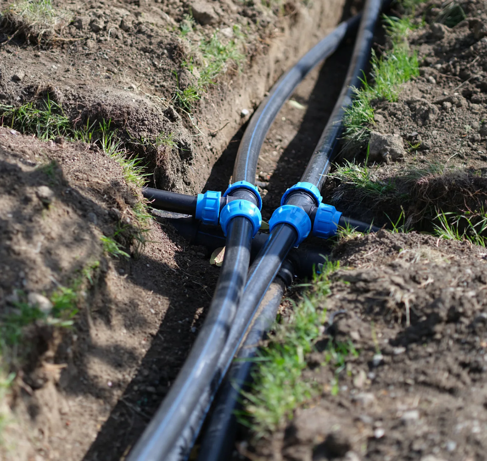
Everything above says the same thing: soil quality is the design. This is what must appear in the specification so the E′ you assumed is the E′ you get.
| Class | Description |
|---|---|
| I | Crushed rock: 100% passing 1-1/2 in, ≤25% passing 3/8 in, ≤15% passing #4, ≤12% fines |
| II | Clean coarse-grained soils, USCS GW, GP, SW, SP (up to 12% fines) |
| III | Coarse-grained with fines (GM, GC, SM, SC); sandy/gravelly ML, CL with ≥30% retained on #200 |
| IV | Fine-grained soils with <30% retained on #200 (ML, CL) |
| V | High-compressibility silts/clays and organics (MH, CH, OL, OH, Pt) — not recommended for pipe installation; must not be used as Engineered Installation embedment |
Source: PPI Chapter 7 (Nov 2025), Table 1, p.7-2. Classes descend in stiffness when compacted. Classes I–II are cohesionless and best compacted by vibration; III–IV are cohesive and best compacted by pressure, impact or kneading. The plant on site must match the soil that came out of the trench, not whatever was already on the job.
One criterion routinely omitted: stable materials interlock to provide structural support, and are angular-particle native soils, sands and gravels. Unstable rounded-particle materials do not interlock and are unsuitable for foundation, bedding, haunching and initial backfill. Embedment must be free of refuse, organic material, cobbles, boulders, large stones or frozen soil (WL Plastics WL113, pp.2-3). Rounded river gravel looks like clean granular backfill on a delivery ticket and behaves like ball bearings in the haunch.
| Pipe diameter | Maximum embedment particle size |
|---|---|
| Up to 4 in | 1/2 in (12.7 mm) |
| 6 to 8 in | 3/4 in (19 mm) |
| 10 to 16 in | 1 in (25.4 mm) |
| 18 in and larger | 1-1/2 in (38 mm) |
Source: PPI Chapter 7, Table 2, p.7-3. Separately, final backfill should be limited to 3 in (76 mm) maximum particle size to ease future excavation (p.7-8) — a maintenance provision, and the one most often struck out in value engineering. On a campus loop that will be dug up for future building connections, defend it.
For Engineered Installation, Class I or II material is placed on the trench bottom and left uncompacted: 4 in (102 mm) thick for pipe under 60 in diameter, 6 in (152 mm) for 60 in and larger, plus at least 2 in (51 mm) more if the trench bottom is rock or contains cobbles (PPI Chapter 7, p.7-7).
The haunch zone is where installations are won or lost. PPI states plainly that a successful installation depends on correct placement and compaction there. Place the first few lifts so embedment can be shovel-sliced into the haunches. Preferred alternatives are flowable fill, or compacting Class I/II soils with saturation and vibration per ASTM F1668. Flowable fill used in the haunch should also be used as bedding. Initial backfill should reach the same stiffness as the haunch zone and must not be compacted directly over the top of the pipe (PPI Chapter 7, p.7-7).
Initial backfill provides structural support to about 75% of the pipe OD. Above that it is padding, limiting particle size against the pipe and cushioning final backfill dumped into the trench. In a sloped-wall trench the padding can be a 12 in (305 mm) cover and need not span the full width (PPI Chapter 7, p.7-8). Under paved surfaces, crossing pipelines or waterways, final backfill goes in lifts compacted to ≥95% ASTM D698 Standard Proctor, or per the owner’s requirement; Class V should not be used unless specifically required (p.7-8). Embedment is placed in layers typically 6 to 12 in (150–300 mm) (WL113, pp.2-3).
This one produces genuine site disputes, because the wrong test gets specified. For Classes I or II the preferred laboratory maximum density test is vibratory — ASTM D4253 (vibratory table) or ASTM D7382 (vibratory hammer), with D7382 considered more reliable. For Classes III or IV it is the Standard Proctor, ASTM D698. Field density uses sand cone or nuclear gauge, but the nuclear gauge is not appropriate for Class I soils or Class II gravels (PPI Chapter 7, p.7-3).
So a specification calling for crushed rock embedment, then demanding 95% Standard Proctor verified by nuclear gauge, has asked for a test that does not properly apply using an instrument not appropriate for the material. That clause will be argued at the first density failure. Write the test to match the soil class.
Flowable fill (ASTM CLSM) is a fluid mix of Portland cement, soil and water hardening into a solid mass typically 2 to 5 times stiffer than compacted soil. Placed as a fluid, the pipe may float: use restraints or ballast, or place the first lift just below flotation level and the rest after initial set, typically 3 to 5 hours. Check the DR against the unconstrained wall buckling equation so hydrostatic pressure from the fill does not buckle the pipe. Flowable fill can reach 120–140 °F (49–60 °C) during the first 2 days, and the effect on polyethylene would be negligible (PPI Chapter 7, pp.7-8 to 7-9).
Connect that last point to the temperature section: a short 140 °F excursion during cure is a transient outside the wall, not a sustained service temperature, and does not invoke FT = 0.50.
Flotation is a design trigger independently of flowable fill: provisions apply to pipe over 24 in (600 mm) without H20/HS20 loading, or over 36 in (900 mm) with it (WL113, p.3). PPI adds that flotation potential exists wherever ground water is above the pipe invert and cover is less than two diameters (Chapter 6, p.210). An empty chilled water main in a high water table before commissioning is the classic case.
Where people enter trenches, any excavation over 5 ft (1.5 m) deep or in unstable soil must have sloped or benched walls, trench boxes, or shoring per OSHA or the governing jurisdiction; excavations 20 ft (6.1 m) and deeper need a support system designed by a professional engineer. A competent person must declare excavations safe for entry each day, after rain, and after significant water events — including trenches under 5 ft (PPI Chapter 7, p.7-4).
The trench box also has a structural consequence: embedment must be compacted against the trench wall, not against the box. Compacting against a box that is later moved leaves a void that can cause excessive deflection; box offset is 2 ft maximum (PPI Chapter 7, p.7-5). This is an invisible failure path. The density test passes, the box moves forward, and the soil support the calculation assumed is gone.
This is the mechanism most specific to buried polyethylene, and where instinct from steel and ductile iron misleads.
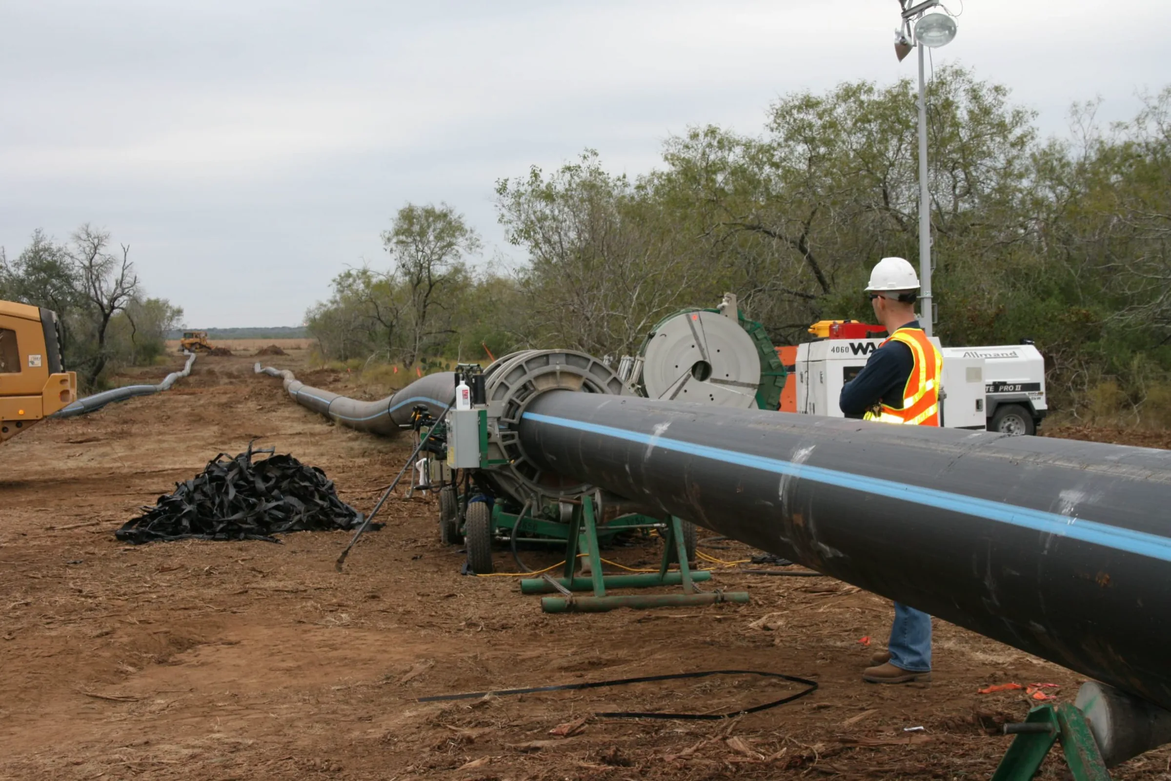
Start with the rule that simplifies everything. PE pressure piping must use fully restrained joints, or partially restrained joints plus external restraints. Systems joined by heat fusion, electrofusion, flanges and MJ adapters are fully restrained and do not require external joint restraints or thrust blocks (PPI Chapter 7, p.7-11). A fully fused loop needs no thrust blocks at elbows and tees — a real cost and programme saving against ductile iron, and a legitimate line in a value comparison.
Pressurising PE expands the diameter slightly. In a continuously fused line the length cannot decrease, so longitudinal tension — the Poisson force — develops. Where PE connects in-line to unrestrained mechanical couplings or bell-and-spigot PVC or ductile iron, that cumulative shortening can pull joints apart. Conventional thrust blocks resist fluid thrust that would push a fitting off the pipe end, and cannot counteract forces that pull the pipe end out of a joint. Snaking pipe in the trench is generally not effective. The remedies are external joint restraints, an in-line anchor block, or both (PPI Chapter 7, p.7-11 and Appendix A p.7-14).
The magnitude is calculable. Fv = σl · Awall, where σl = νlong(σθ)·WP + νshort(σθ)·POS. Long-term Poisson’s ratio νlong = 0.45 applies to working pressure; short-term νshort = 0.35 to occasional surge. Awall = π · DM · t, with DM = OD − t; hoop stress is computed on the mean diameter per AWWA M55 (PPI Chapter 7, Appendix A, p.7-15). Thermal force adds: FT = σT · Awall, and total pullout design force is the sum.
| Temperature zone | σT, typical construction (psi) | σT, Best Practices (psi) |
|---|---|---|
| Warm | 255 | 110 |
| Moderate | 290 | 150 |
| Cold | 300 | 180 |
Source: PPI Chapter 7, Appendix A Table A.2, after Stewart and Bilgin 2020, p.7-16. Best Practices construction is intended to minimise thermal stresses arising during installation.
Worked, for the same 8 in DR 11 line at 100 psi and no surge (our arithmetic on PPI’s equations): t = 0.784 in, DM = 7.841 in, Awall = 19.31 in². Hoop stress = 100 × 7.841 / (2 × 0.784) = 500 psi; longitudinal = 0.45 × 500 = 225 psi, giving about 4,350 lb. Add thermal in a warm zone with typical construction, 255 × 19.31 ≈ 4,930 lb, for a total pullout design force near 9,300 lb. With Best Practices construction the thermal part drops to about 2,100 lb and the total to about 6,500 lb.
Nine thousand pounds withdrawing an 8 in pipe from a mechanical coupling is not a detail to leave to the installer. Note the sensitivity: the gap between typical and Best Practices installation is about 2,800 lb. Installation discipline is worth roughly 30% of the restraint demand.
PE’s thermal expansion coefficient is about 1 × 10⁻⁴ in/in/°F (≈1.8 × 10⁻⁴ mm/mm/°C), with the field rule of thumb “1/10/100”: roughly 1 inch of length change per 10 °F per 100 ft (≈2.5 cm per 5.6 °C per 30 m). Unrestrained change is ΔL = L·α·ΔT (PPI Chapter 6, Eq. 4-1, pp.243-244). For a restrained line, σ = E·α·ΔT and end thrust F = σ·AP. PPI makes a point lost in the usual “plastic moves a lot” objection: although PE’s expansion coefficient is much larger than non-plastics, its low modulus greatly reduces the thrust from restrained expansion, and this thrust imposes no problem on thermal fusion connections (PPI Chapter 6, Eq. 4-2 and 4-3, p.244).
Our arithmetic, same pipe with ΔT = 66 °F: σ = 726 psi at the short-term modulus, about 14,000 lb thrust — but 186 psi at the 50-year modulus, about 3,600 lb. Stress relaxes roughly fourfold as the material creeps. Hence an expansion coefficient that would alarm in a rigid material is manageable in PE, and the modulus must match the duration of the event analysed.
Hence the sequencing requirement. Placing pipe that has been in direct sunlight into a cooler trench causes contraction that can pull joints out at mechanical couplings or buried structures. Allow pipe to cool before connecting to an anchored joint, flange, or any fitting needing pull-out protection; covering with soil helps. Make the final connection after the pipe reaches operating temperature (PPI Chapter 7, p.7-6; corroborated Chapter 6 p.243). Put a number on it: a 300 ft run laid at 110 °F and commissioned on 44 °F water — inside the 42–45 °F supply band cited above — sees ΔT = 66 °F — about 20 inches of contraction by the “1/10/100” rule if free to move. It is not free, so that movement becomes the pullout force above, concentrated at the weakest joint. On a hot-climate job this belongs in the method statement.
Outlet connections may be made after placement in the trench with flanges, mechanical couplings or electrofusion couplings. Butt fusion can be done in the trench, but placing and removing the machine must not disturb the piping. Fittings 16 in and above — elbows, tees, wyes, crosses — should not be joined to more than one pipe length before placement without additional precautions. Lifting such assemblies frequently causes damage and is not recommended (PPI Chapter 7, p.7-10).
The electrofusion procedure, in PPI’s order: (1) prepare the pipe — cut square, clean, and scrape to expose clean virgin material with purpose-made tools, cleaning where required with water or 90% isopropyl alcohol, no additives, not denatured; (2) mark stab depth with a non-petroleum marker; (3) align and restrain in a clamping fixture, re-rounding large diameters first if needed; (4) apply current via the control box, reading the fitting’s barcode; (5) cool and remove clamps — premature removal or strain on an uncooled joint is detrimental; (6) document the fusion (PPI Chapter 9, pp.333-335).
Step 1 is the one that fails. Scraping is not cleaning: an unscraped surface carries oxidised material that will not fuse, and looks identical to a scraped one once the fitting is on. Note the marker restriction too — a petroleum-based marker introduces exactly the class of hydrocarbon the FE table treats as permeating.
For joints that will be inaccessible after backfill, the QA argument is decisive: the control box that applies current also monitors the critical fusion parameters — time, temperature, pressure — and stores data for each joint, downloadable for documentation and inspection (PPI Chapter 9, p.335). On a buried loop that record is the only joint-by-joint evidence that will exist once the trench closes. Applicable standards: ASTM F2620 for butt and socket fusion, PPI TN-13/TR-33/TR-41 for unlike PE resins, and ASTM F1924, ASTM F1973 and AWWA C219 for mechanical connections (PPI Chapter 9, p.335).
One figure this article deliberately does not give: a numeric electrofusion-versus-butt-fusion joint strength comparison. That percentage circulates widely but appears only in vendor material, and we could not confirm it in PPI Chapter 9 or ASTM F2620. Treat it as Coming soon pending a primary source.
Mechanical compression couplings comprise a body, compression nut, elastomer seal, a stiffener, and sometimes a grip ring. There are three categories: seal only; seal plus some pullout restraint; and seal plus full restraint against pullout. The pipe wall must be supported by the stiffener under the seal ring and under the gripping ring; lack of support can cause loss of seal or loss of pullout grip. The style is normally used on service lines 2 in IPS and smaller; stab-type fittings from 1/2 in CTS to 2 in IPS are all ASTM D2513 Category I — seal and full restraint (PPI Chapter 9, pp.336-337).
Read that against the pullout section: a seal-only coupling in a buried PE line is, by design, one of the unrestrained joints those forces act on. Specifying “compression coupling” without the restraint category leaves the joint’s most important property to the supplier.
For larger sizes, bolt-type couplings (1-1/4 in IPS and up) join PE to PE, PVC, steel or cast iron by compressing a gasket around each pipe end, and may or may not include a grip ring exceeding the pipe’s yield strength. A stiffener is needed here too, and when connecting to the bell of ductile iron or PVC a stiffener should be added to the pipe ID — either fixed-diameter (mainly smaller services, must be sized for correct press fit) or split-ring (normally stainless, thin but strong, no flow disturbance). The exact SDR of the PE must be specified when ordering (PPI Chapter 9, pp.337-340). That is a procurement failure waiting to happen. The stiffener sizes to the bore, which depends on DR. Order without stating SDR and it will not fit — precisely the condition PPI says causes loss of seal or grip.
| Condition | Minimum long-term radius | For 8.625 in OD |
|---|---|---|
| DR 9 | 20 × OD | 14.4 ft |
| DR 11 and 13.5 | 25 × OD | 18.0 ft |
| DR 17 and 21 | 27 × OD | 19.4 ft |
| Fitting or flange present in the bend | 100 × OD | 71.9 ft |
Source: PPI Chapter 7, Table 4, pp.7-9 to 7-10; multipliers are PPI’s, the right column our arithmetic for one diameter. The 100 × OD case is observed for about 5 diameters either side of the fitting and includes tapping tees and service saddles. All include a safety factor against kinking of at least 2. PE may be cold bent in the field without affecting the working pressure rating, and typically bends without great effort to about 70 diameters. The 4× jump is the clause to watch: a service saddle dropped into a curved lateral turns an 18 ft acceptable radius into a 72 ft one, and the pipe is already laid.
On damage: minor surface abrasion under 10% of wall thickness is not a concern, but pipe with gouges or cuts exceeding 10% of wall thickness should not normally be used unless reviewed by the Project Engineer; the affected length may be cut out and the rest reused. Pipe must not be dumped, dropped, dragged over hard surfaces, or rolled into a trench (PPI Chapter 7, p.7-5). For 8 in DR 11 with a 0.784 in wall that threshold is 0.078 in — under 2 mm, shallower than most inspectors would flag by eye. Write it into the checklist with the number on it. The link to slow crack growth is direct: a gouge is a stress concentration, and stress concentration moves failure from the ductile branch to the brittle one.
Testing has an unusually clean criterion: allowable leakage for fused PE pipe is zero. PE water pipe is tested per ASTM F2164; allowable leakage for a system including non-PE pipe and fittings is set by the engineer (PPI Chapter 7, p.7-13).
You cannot find it later. PE is non-metallic, so once buried, metal detector locators are ineffective. Tracer wire shall be placed no more than 6 in (152 mm) above the pipe, installed simultaneously along the entire pipeline and all service connections, spliced with underground-rated devices, with continuity verified before acceptance. No bare tracer wire is acceptable. Minimum #12 AWG solid copper, copper-clad steel, or braided stainless with minimum 450 lb break load, and minimum 30 mil HDPE insulation; provide a sacrificial anode per ASTM B843. Warning ribbons, if used, go 3 ft (0.9 m) or less below grade (PPI Chapter 7, p.7-9). On a campus this has the longest tail: the loop will be crossed by electrical, fibre and drainage works for decades. A traceable line is found by the next surveyor; an untraceable one by the bucket.
Contaminated soil can rule HDPE out entirely. PE is not attacked by inorganic chemicals and will not rust or corrode galvanically. However, PE pipe and elastomeric gaskets may degrade or suffer permeation in soils contaminated with organic solvents or petroleum products, or their vapours; if permeation occurs, water contamination may result. For new work, remediate or remove the soil, reroute, or protect with encasement; PPI directs designers to Statement N and the BTEX calculations in HDPEapp.com (based on Koo 2012). Metallic valves, fittings and harnesses may still suffer in corrosive soils and should be wrapped, coated or cathodically protected (PPI Chapter 7, p.7-4). This is the same physics as the FE = 0.5 derating, arriving from outside the pipe. On a brownfield site, or a route past a former workshop, the soil survey is a piping material decision.
Where the line comes up. PE entering or exiting a casing, or passing through a building wall, vault or access hole, must be protected against shear and bending from settlement: install on compacted bedding or flowable fill for at least 2 pipe diameters where it exits, wrap with elastomeric sheet at casing entry, then seal the annulus mechanically or with non-shrink cement or chemical grout against soil infiltration. All appurtenances — tees, elbows, valves, air relief valves, hydrants — must be independently supported and shall not rely on the pipeline for support (PPI Chapter 7, pp.7-10 to 7-11). The transition into a mechanical room is the highest-risk metre of the run. Differential settlement between a piled building and bedded soil, a change from restrained to potentially unrestrained jointing, and the pullout forces calculated earlier all land at one point.
Our pillar page covers condensation control and vapour barriers generally; the buried-specific point is narrower. For below-ambient systems, condensation control is often the overriding design objective, and water-resistant vapour-retarder jacketing or mastics must be specified. If process temperatures fall below ambient even briefly — during shutdowns, say — a vapour retarder is required. It must restrict moisture migration through facing, joints, seams, penetrations, hangers and supports. Wet insulation degrades fast, and a moisture-saturated system can lose most of its thermal performance (National Insulation Association, Insulation Outlook, “Below Ambient Piping Insulation Systems”). We could not source a single published figure putting a percentage efficiency loss against a percentage moisture gain; treat any such number as Coming soon.
Below grade the vapour drive is permanent and the inspection opportunity zero — the argument for factory pre-insulated pipe over field-applied insulation on a buried run. Such systems exist as engineered products. GF Piping Systems COOL-FIT uses a PE100 carrier pipe, closed-cell GF PUR (polyurethane) foam, and a PE outer jacket, rated −50 °C to +60 °C (−58 °F to +140 °F) and up to 16 bar (232 psi) at SDR 11 and 20 °C (68 °F) media temperature, designed for indoor, outdoor and underground installation (GF Piping Systems, COOL-FIT product information). We cite a competitor because it is the clearest published evidence that buried insulated chilled water in PE100 is a commercially available engineered configuration, not an improvisation. It is not a product we supply.
Almost everything above concerns pipe sizes we do not make. Better said here than in an email after you have specified us.
IFANNova is a French brand; our products are manufactured by Zhuji Fengfan Piping in Zhuji, Zhejiang, China. Nothing in our range is made in France, and we will not let a specification imply otherwise. The manufacturing base is 30+ years old, employs 1000+ people, exports to 118+ countries and covers 120,000 ㎡.
| Question this article raises | Our position |
|---|---|
| DN150–DN400 buried chilled or condenser water mains | We cannot supply these. Our pressure-pipe ceiling is Φ110 — UPVC 806 PN16 and HDPE PN16, both Φ20–Φ110; PPR PN20 stops at 32 mm. Our PVC 902 line reaches Φ160 in the 1902 fittings only — the 902 pipe stops at Φ110 — and 902 is non-pressure drainage and is excluded from chilled water pressure duty (per our catalogue) |
| HDPE pipe | HDPE PN16 marked to DIN 8077/8078 (per our catalogue), Φ20–Φ110, with 603/604 weld-free compression fittings (per our catalogue) |
| PPR | PPR PN20, series 1103 — 20/25/32 mm only; 1138 fittings, 75 items (per our catalogue) |
| UPVC | UPVC 806 PN16, Φ20–Φ110; 1806 fittings, 203 items (per our catalogue) |
| PVC drainage / PEX / brass | PVC 902 drainage, 902 pipe Φ32–Φ110 with 1902 fittings Φ32–Φ160 — non-pressure drainage, not for chilled water pressure duty; PEX 2114/2121, 16–32 mm; brass 2405 (per our catalogue) |
| DR/SDR-designated PE4710 or PE100 to the classes tabulated above | Coming soon — our HDPE line is published as PN16, marked to DIN 8077/8078 (per our catalogue), not as a DR-designated PE4710 range |
| ASTM D3350 cell class and PENT hours for our HDPE | Coming soon |
| Fusion equipment and procedures for buried mains | Not supplied. Our HDPE range is joined with 603/604 compression fittings (per our catalogue) |
| Pre-insulated buried pipe | Insulation can be supplied alongside pipe, but we publish no specification for it — Coming soon |
| Certifications | SKZ, CE, WRAS, DVGW, SGS, ISO 9001, ISO 14001. Certificate numbers: Coming soon |
Our range fits a project like this at the small end: Φ20–Φ110 laterals and service connections branching off a main we did not supply. At those diameters maximum embedment particle size is 1/2 in up to 4 in pipe, the Basic Installation criteria are frequently satisfiable, and compression fittings remove fusion equipment from the trench. They do not remove the restraint question. A coupling’s category — seal only, partial, or full restraint against pullout — decides whether the Poisson and thermal forces calculated above have anything holding them. Ask us for the restraint category of the 603/604 series before detailing the connection. Where we cannot evidence it, the honest answer is Coming soon, and you should design in an external restraint.
If your project needs Φ20–Φ110 HDPE, UPVC, PPR, PEX or brass for branch and service-level work, send us the schedule and we will quote against our published catalogue ranges. If it needs DN150 and above, we will say we cannot supply it rather than quote something we do not make. Where a certificate number, a cell class or an insulation specification is not yet published on our side, the answer here and in our quotation is the same: Coming soon.
Material comparison sourced to named test methods, the constraints that actually govern sizing, and why condensation — not pressure — is what fails a…
A worked chilled water pipe sizing example: cooling load to flow, flow to diameter, with the velocity and pressure-drop limits that govern each step and where the…
What one floor of chilled water branch pipework actually consumes: valve authority, strainer sizing, and the fitting counts that stop a site when they are missed.
