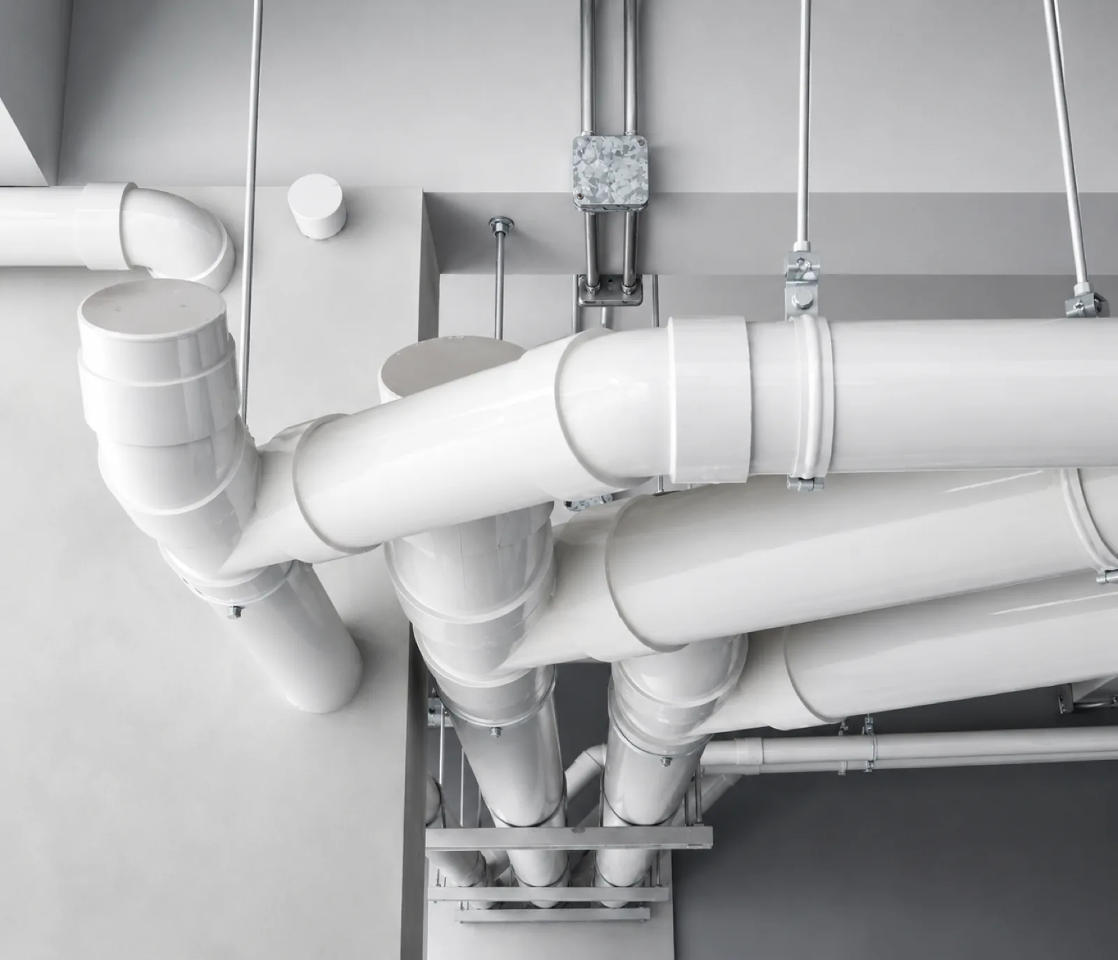
A pressure pipe forgives a lot. Push water through it hard enough and it will get where it is going regardless of whether the installer ran it level or in a lazy S around a column. A drainage pipe forgives almost nothing, because the only force moving anything through it is gravity acting on a fall you decided on a drawing and someone else set with a spirit level in a trench.
That is why this guide is organised around gradient rather than around diameter. Most uPVC drainage content is a size table, and size tables are the least decisive part of the problem. We will deal with all three axes — size, gradient, connection — and be explicit about which numbers come from a published standard, which come from a manufacturer’s installation manual, and which are our own commercial position.
One scope note first, and it needs stating precisely because it is the detail most often garbled. Our PVC 902 pipe runs Φ32 to Φ110 mm; the matching 1902 fittings run Φ32 to Φ160 mm (per our catalogue). Those are two different ceilings and quoting the range as a single “Φ32–160” span is wrong — you cannot buy Φ160 902 pipe from us. The whole series is non-pressure. Non-pressure is the defining characteristic of the product, not a footnote, because a large share of drainage failures come from treating a gravity pipe as though it had a pressure rating. It does not. It carries partly full flow downhill under atmospheric conditions, and that is the only duty we describe for it here.
This is the first place specifications go wrong, and it costs more than a gradient error because it surfaces at approval stage.
PVC-U sanitary pipework inside buildings — soil stacks, waste branches, the pipework from an appliance to the stack — sits under BS EN 1329. Below-ground uPVC gravity drainage, the run from the building to the sewer or the treatment plant, sits under BS EN 1401. Both are named in the material tables of the UK’s Approved Document H (2015 edition): EN 1329 in Table 4, covering sanitary pipework, and EN 1401 in Table 7, covering below-ground gravity drains [HM Government, The Building Regulations 2010, Approved Document H, 2015 edition, Table 4 p.11 and Table 7 p.16].
Two things follow. First, a tender asking for “uPVC drainage pipe to EN 1401” for a soil stack in a twelve-storey residential block is internally inconsistent, and someone should raise it before the order. Second, the standard you name changes what we are being asked to supply. Wavin, whose solvent-weld soil manual we cite below, states its own 110 and 160 mm solvent soil fittings as PVC-U to BS EN 1329-1:2000 — an illustration of the above-ground standard in commercial use, not a statement about our product [Wavin, Product & Installation Manual — Solvent Weld Soil Plumbing System].
The certifications we hold as a company are SKZ, CE, WRAS, DVGW, SGS, ISO 9001 and ISO 14001. Certificate numbers are Coming soon, and we will not claim a product-standard conformity mark for the 902 series that we cannot put a certificate number behind. If your project requires documented EN 1329 or EN 1401 conformity for the drainage line, ask us and we will answer against the actual paperwork.
Before any flow calculation there is a floor, and it is set by service rather than by hydraulics. Approved Document H para 2.33 puts it plainly for below-ground drains: a drain carrying foul water must be at least 75 mm internal diameter, and a drain carrying effluent from a WC or trade effluent must be at least 100 mm internal diameter [Approved Document H (2015), para 2.33, p.16].
Note that this is internal diameter, and that it is a minimum you cannot calculate your way underneath. If the hydraulics say a WC branch could run at 75 mm, the answer is still 100 mm, because the constraint is solids transport and blockage risk rather than capacity.
Above ground, discharge stacks have their own minimum diameters, again with service conditions attached rather than pure flow limits [Approved Document H (2015), Table 3 ‘Minimum diameters for discharge stacks’, p.10]:
| Stack diameter | Maximum capacity | Condition attached |
|---|---|---|
| 50 mm | 1.2 l/s | No WCs connected |
| 65 mm | 2.1 l/s | No WCs connected |
| 75 mm | 3.4 l/s | Not more than 1 WC with outlet less than 80 mm |
| 90 mm | 5.3 l/s | — |
| 100 mm | 7.2 l/s | — |
The right-hand column is the part people drop when copying the table into a design note. A 65 mm stack is not a 2.1 l/s stack in general; it is a 2.1 l/s stack provided no WC discharges into it. Strip the condition and the table becomes actively misleading.
Approved Document H does not itself perform flow-based sizing by discharge units. It points elsewhere for that: para 2.63 states that “BS EN 12056 describes the discharge unit method of calculating flows”, and para 1.39 lists BS EN 12056 as the alternative approach, noting that “System III is traditionally in use in the UK” [Approved Document H (2015), paras 1.39 p.12 and 2.63 p.22].
EN 12056-2 converts appliance loading into a design flow through a square-root relationship:
Qww = K × √(ΣDU), where Qww is the wastewater flow rate in l/s, K is a frequency factor, and ΣDU is the sum of discharge units [ABCB / Lucid Consulting Australia, Sanitary Plumbing & Drainage Pipe Sizing Final Report v1.1, Executive Summary].
The frequency factor is where building type enters the calculation, and it moves the answer substantially [same source]:
| Usage pattern | Example buildings | K |
|---|---|---|
| Intermittent use | Dwelling, guest house, office | 0.5 |
| Frequent use | Hospital, school, restaurant, hotel | 0.7 |
| Congested use | Toilets and showers open to public use | 1.0 |
| Special use | Laboratory | 1.2 |
Now the caveat most secondary summaries of EN 12056-2 get wrong, and the single most useful point in this section. An appliance does not have one discharge unit value. The DU depends on which System — 1, 2, 3 or 4 — the design uses. The government-commissioned Australian review reports the values as ranges for exactly that reason, each “dependent on which drainage system is selected (System 1, 2, 3 or 4)” [ABCB / Lucid Consulting Australia, Final Report v1.1, section 2.3]:
| Appliance | Discharge unit range (l/s) |
|---|---|
| WC with 6.0 L cistern | 1.2 to 2.0 |
| Sink (single or double) | 0.5 to 1.3 |
| Shower (without plug) | 0.4 to 0.6 |
| Basin | 0.3 to 0.5 |
Note also that EN 12056-2 discharge units are expressed in l/s. They are not the dimensionless fixture units used in some other national systems, and the two must not be substituted for one another.
The Systems differ by the design filling degree of the branch discharge pipe, which is exactly why the DU value moves with the System [ABCB / Lucid Consulting Australia, Final Report v1.1, section 4.2.1, on BS EN 12056-2:2000 Section 4.2]:
| System | Branch pipe type | Design filling degree |
|---|---|---|
| System 1 | Partly filled branch discharge pipes | 0.5 (50%) |
| System 2 | Small bore branch discharge pipes | 0.7 (70%) |
| System 3 | Full bore branch pipes, each branch separately connected to the stack | 1.0 (100%) |
| System 4 | Separate black water / grey water discharge stack system | — |
The practical consequence shows up in Table 4 of the standard, which links hydraulic capacity Qmax to nominal diameter for unventilated discharge branches across a range of 0.40 to 2.5 l/s. The permitted diameter for a given flow is not the same across Systems. A branch at Qmax 0.8 l/s can use DN 50 under System 1 but is not permitted at that size under System 2 or 4. A branch at Qmax 2.25 l/s can use DN 90 under System 1 with no WCs connected, or DN 80 under Systems 2 or 4 with not more than one WC connected [ABCB / Lucid Consulting Australia, Final Report v1.1, commentary on BS EN 12056-2:2000 Table 4]. Stack sizing uses two separate tables depending on ventilation arrangement: Table 11 for primary ventilated stacks, Table 12 for secondary ventilated stacks, the latter giving higher capacity per diameter [same source, sections 4.2.11–4.2.12].
What we could not verify. We were unable to open the full text of EN 12056-2:2000 — it is a paywalled BSI/CEN document. So we are not publishing a single DU number per appliance, and not reproducing the numeric rows of Tables 11 and 12. Secondary sources disagree on per-appliance DU values (one puts a basin at 0.3, another at 0.5), and the report above shows why: the value is System-dependent. If your design needs exact figures, buy the standard.
Here is the core of it. A drain that is too flat leaves solids stranded because the flow lacks the velocity to carry them. A drain that is too steep can, in the classic account, run the liquid away ahead of the solids. Either way the end state is the same: a blockage in a buried pipe, found by a tenant, excavated at somebody’s cost.
Approved Document H Table 6 gives recommended minimum gradients for foul drains, and the structure matters as much as the numbers. Gradient is conditioned on both diameter and peak flow, and two rows carry footnote conditions [HM Government, Approved Document H (2015), Table 6 ‘Recommended minimum gradients for foul drains’ plus Notes * and †, p.16]:
| Pipe size | Peak flow | Minimum gradient | Maximum capacity | Footnote condition |
|---|---|---|---|---|
| 75 mm | Less than 1 l/s | 1:40 | 4.1 l/s | — |
| 75 mm | More than 1 l/s | 1:80 | 2.8 l/s | — |
| 100 mm | Less than 1 l/s | 1:40 | 9.2 l/s | — |
| 100 mm | More than 1 l/s | 1:80 | 6.3 l/s | * Minimum of 1 WC discharging into it |
| 150 mm | More than 1 l/s | 1:150 | 15.0 l/s | † Minimum of 5 WCs |
Read the third and fourth rows together and the counter-intuitive part appears. The flatter gradient of 1:80 is permitted on a 100 mm drain at the higher peak flow, not the lower one — and then only where at least one WC discharges into it. The WC provides the flushing event that clears the pipe; without it the flatter grade is not sanctioned. The 150 mm row is stricter: 1:150 appears only where a minimum of five WCs discharge into the run.
This is why “lay it at 1:80” as a site rule of thumb is dangerous. On a 100 mm drain serving a WC above 1 l/s it is the tabulated figure. On a 150 mm drain with two WCs it is not, and 1:150 is not available either, because the footnote condition fails.
Two scope warnings on the table above, and we would rather over-state them than have this article misused. These are the England Building Regulations guidance figures, not EN 12056-2 requirements. We were not able to open EN 12056-2’s own branch gradient provisions expressed in the EN-native percentage or ratio form. If you are designing for a French or wider EU project, do not present the 1:40 / 1:80 / 1:150 ratios as though they were European standard requirements — they are not, and a reviewer who knows the difference will say so. Second, these are gradients for below-ground foul drains and do not transfer to above-ground branch pipework, which is governed separately and differently.
This distinction is regularly lost. For below-ground drains you get a minimum gradient. For above-ground branch discharge pipes, Approved Document H Table 2 gives a band — a minimum and a maximum — expressed as millimetres of fall per metre of run rather than as a ratio [HM Government, Approved Document H (2015), Table 2 ‘Common branch discharge pipes (unventilated)’ and Diagram 3, p.9]:
| Appliance | Minimum pipe size | Gradient band | Length condition |
|---|---|---|---|
| WC, outlet more than 80 mm | 100 mm | 18 to 90 mm/m | See footnote below |
| Washbasin / bidet | 30 mm | 18 to 22 mm/m | At 1.7 m length |
| Washbasin / bidet | 40 mm | 18 to 44 mm/m | At 3.0 m length |
| Washbasin / bidet | 50 mm | 18 to 44 mm/m | At 4.0 m length |
The WC footnote is the one worth memorising for congested risers and refurbishment work: the 18 mm/m minimum may be reduced to 9 mm/m on long drain runs where space is restricted, but only if more than one WC is connected [same source]. That is a genuine escape route when a ceiling void will not give you the fall — and it is conditional, so it is not available on a single-WC branch.
Note also how tightly the 30 mm washbasin row is drawn: an 18 to 22 mm/m band at 1.7 m. Going up to 40 mm buys you both a longer permitted run and a much wider gradient band. That is a design lever worth pulling before you start arguing with the structural drawings, and all three sizes sit squarely inside our PVC 902 drainage pipe and fittings range — Φ32 × 1.6, Φ40 × 1.6 and Φ50 × 1.8 mm respectively (per our catalogue).
A drainage system is a series of joints with pipe in between, and most of what goes wrong at commissioning goes wrong at a joint. Solvent welding is not gluing. It is a chemical fusion process with preparation steps and timing windows, and skipping them produces joints that look correct and are not.
Preparation. Square the pipe end, deburr it, and maintain a 10% to 15% chamfer. Dry-fit before committing. Where a primer is used, apply the solvent cement while the primer is still wet and within five minutes of primer application [Oatey, Complete Guide to Solvent Welding PVC, CPVC & ABS Pipe].
Assembly. Insert the pipe into the fitting quickly, give it a quarter turn, and hold it firmly for at least 30 seconds. Wipe away excess cement to keep the joint clean [same source]. The quarter turn distributes cement around the circumference; the 30-second hold resists the tendency of the joint to push itself back out before the cement grabs.
Cement selection by diameter. Larger pipe diameters require heavier-bodied cements to fill the gap between pipe and fitting properly; the source gives no numeric diameter threshold. One-step cements of the Oatey Fusion type are suited to PVC pipe up to two inches in diameter in non-pressurised applications [same source]. Our 902 pipe tops out at Φ110 × 2.2 mm, and our 1902 fittings reach Φ160, so if your schedule includes a Φ160 fitting on someone else’s pipe, take the body grade from the datasheet of the cement you are using rather than from a rule of thumb.
A degreasing cleaner is a separate consumable from the cement. This catches out buyers doing a materials take-off. Wavin’s soil system specifies Degreasing Cleaner No.1 and Solvent Cement No.2 as two distinct products, and gives coverage for 110 mm pipe as approximately 32 joints per 250 ml can of cleaner and 11 joints per 250 ml can of cement [Wavin, Solvent Weld Soil Plumbing System manual, Table 7 ‘Cleaner/Solvent Cement Usage Guide’, p.4]. The ratio is the useful part: you will get through roughly three times as many cans of cement as of cleaner on 110 mm work. Order accordingly.
These two terms are used interchangeably on site and mean different things. Set time is “the time required for the assembled joint to develop sufficient handling strength”. Cure time is “the time required for the solvent weld to reach the strength needed for testing or service”. As Oatey puts it, “a joint may feel dry or firm before it has developed the strength needed for pressure or service” [Oatey, How Long Does PVC Glue Take to Dry?].
The most widely circulated numeric schedule is IPS Corporation’s Weld-On table. Its initial set schedule, at 60–100°F (16–38°C), runs as follows [IPS Corporation, Weld-On Solvent Cement Average Set and Cure Times]:
| Pipe size | Initial set at 16–38°C | Initial set at −18 to 5°C |
|---|---|---|
| 20–40 mm (½”–1¼”) | 2 minutes | 10 minutes |
| 50–63 mm (1½”–2″) | 5 minutes | 15 minutes |
| 75–200 mm (2½”–8″) | 30 minutes | 12 hours |
| 250–380 mm (10″–15″) | 2 hours | 24 hours |
| 380 mm and above | 4 hours | 48 hours |
In damp or humid weather, allow 50% more set time [same source]. Look at the 75–200 mm row across the two temperature columns: 30 minutes becomes 12 hours. That is a factor of 24, and it is the reason winter drainage programmes slip when they were planned on summer figures.
Joint cure times, at 16–38°C and relative humidity of 60% or less, are conditioned on pressure rating as well as diameter [same source]:
| Pipe size | Cure at up to 160 psi / 11 Bar | Cure at higher pressure rating |
|---|---|---|
| 20–40 mm | 15 minutes | 6 hours at 160–370 psi |
| 50–63 mm | 30 minutes | 12 hours at 160–315 psi |
| 75–200 mm | 1½ hours | 24 hours at 160–315 psi |
| 250–380 mm | 48 hours (at up to 100 psi / 7 Bar) | — |
| 380 mm and above | 72 hours (at up to 100 psi / 7 Bar) | — |
Damp or humid weather again requires 50% more cure time [same source].
Three qualifications on the two tables above. First, Weld-On qualifies its own figures: “These figures are estimates based on testing done under laboratory conditions. Field working conditions can vary significantly. This chart should be used as a general reference only” [IPS Corporation, footnote **]. Second, this is a US table spanning PVC and CPVC, pressure and non-pressure, with cure columns indexed by pressure rating. Applying it to a DN 110 EN 1329 gravity soil stack is an extrapolation, and we flag it as one — we searched for an equivalent EU-published set/cure table specific to EN 1329 non-pressure PVC-U and did not find one. Third, on the question everyone asks next, the ambient temperature window for solvent welding: we found no citable manufacturer limit and will not invent one. Oatey’s guide does not specify application temperature limits, and the Weld-On table extending to −18°C states how long the joint takes, not that working there is approved. Get the limit from the datasheet of the cement you are using.
If you take one installation point from this article, take this one. A solvent-welded PVC-U soil system is rigid — every joint is a fusion. The pipe still expands and contracts with temperature, and because the joints cannot absorb that movement, it must be designed in deliberately with expansion fittings. In our experience this is the most commonly omitted solvent-weld installation requirement on drainage packages; that is an opinion from what we see in the field, not a published statistic.
The magnitude is not trivial. A 6-metre length of PVC pipe will expand or contract approximately 5 to 10 mm for each 10°C rise or fall in temperature [TEPPFA, Guidance Notes for Socket Jointing of PVC-U and PVC-O Pipe Systems for Pressure Applications, p.5]. That figure comes from a pressure-pipe document, so treat it as an indication of PVC’s thermal behaviour rather than a drainage-specific specification.
Wavin’s soil manual gives the requirement in diameter-conditioned form. Provision for thermal movement is required for all solvent weld runs over 3 m for 32, 40 or 50 mm pipe, and over 4 m for 110 or 160 mm pipe, and between any two fixed points 1 m or more apart. Fixed points include fittings supported by socket brackets, changes of direction, and branches from other appliances [Wavin, Solvent Weld Soil Plumbing System manual, ‘Thermal Movement’, p.26]. The “two fixed points 1 m apart” clause is the trap — a short length between a bracketed fitting and a branch can trigger the requirement even when the overall run looks short.
The corollary is a real design decision. A correctly made push-fit ring-seal joint accommodates thermal movement with no expansion fittings required [same source]. So solvent weld versus ring-seal is not only about labour speed or joint integrity — it changes whether you must engineer expansion provision into the run at all. On long horizontal soil runs with many fixed points, that can outweigh everything else.
A related limit from the same manual: the maximum recommended pipe run from trap to stack is 3 m for 40 mm pipe and 4 m for 50 mm pipe. Exceed it and the run must be vented to prevent self-siphonage or induced siphonage — and in a solvent weld system, provision for thermal movement is required as well [Wavin, ‘Maximum Pipe Runs’, p.26].
Gradient set in a trench stays where you put it. Gradient set on brackets stays where the brackets let it. Sagging between supports is a slow, invisible way to lose the fall you designed, and the resulting low point collects exactly what you were trying to move.
Wavin’s Table 9 gives maximum support centres for PVC-U solvent weld soil and waste [Wavin, Solvent Weld Soil Plumbing System manual, Table 9 ‘Maximum Pipe Support Centres’, p.27]:
| Pipe diameter | Vertical (m) | Horizontal (m) |
|---|---|---|
| 21.5 mm | 0.5 | 0.5 |
| 32 mm | 1.2 | 0.5 |
| 40 mm | 1.2 | 0.5 |
| 50 mm | 1.2 | 0.6 |
| 82 mm | 2.0 | 1.0 |
| 110 mm | 2.0 | 1.0 |
| 160 mm | 2.0 | 1.2 |
The gap between the vertical and horizontal columns on small pipe is the point. A 32 mm waste pipe tolerates 1.2 m between vertical supports but only 0.5 m horizontally — a factor of well over two. Vertical pipe is largely supported by its own axis; horizontal pipe carries its weight plus its water content in bending, and it is the horizontal run that holds your gradient. These are Wavin figures for their own system; check them against the manufacturer’s data for the pipe you actually buy, ours included.
Above-ground sanitary pipework, once solvent-welded joints have cured, is air tested. Pipes, fittings and joints should withstand a positive pressure of at least 38 mm water gauge for at least 3 minutes, with every trap maintaining a water seal of at least 25 mm. Smoke testing is not recommended for PVC-U pipes [HM Government, Approved Document H (2015), para 1.38, p.12]. That last point is worth flagging to any site team that has carried a smoke practice over from a different material.
Below-ground drains up to 300 mm use different parameters: pressurise to 110 mm water gauge, hold for approximately 5 minutes, then the pipe should hold an initial 100 mm pressure with a maximum loss of head on a manometer of 25 mm over 7 minutes [Approved Document H (2015), para 2.60, p.21].
Sequencing note: the cure-time discussion above is not academic here. Testing a solvent-welded system before the joints have cured tests the programme, not the pipework.
Our PVC 902 drainage series is non-pressure, supplied in 4 m lengths, with pipe from Φ32 to Φ110 mm and 1902 fittings from Φ32 to Φ160 mm (per our catalogue). Here is the full published wall thickness schedule, every size, not a range with the middle left out:
| Outside diameter (mm) | Wall thickness (mm) |
|---|---|
| 32 | 1.6 |
| 40 | 1.6 |
| 50 | 1.8 |
| 63 | 1.8 |
| 75 | 1.8 |
| 80 | 1.8 |
| 90 | 1.8 |
| 100 | 2.2 |
| 110 | 2.2 |
Two features of that table are worth reading rather than skimming. The wall holds at 1.8 mm across five consecutive diameters from Φ50 to Φ90, which is characteristic of a gravity series: the wall is set by handling and jointing robustness, not by an internal pressure calculation, so it does not scale with diameter the way a pressure pipe’s does. And the step to 2.2 mm arrives at Φ100, not at Φ110 — worth knowing if you are comparing our schedule against a competitor’s on a like-for-like basis.
Mapped against this article:
| Application from this guide | Diameter needed | 902 pipe? | 1902 fittings? |
|---|---|---|---|
| Washbasin / bidet branch (32, 40, 50 mm options) | 32–50 mm | Yes — 32 × 1.6, 40 × 1.6, 50 × 1.8 | Yes |
| Discharge stack, 50 / 65 / 75 / 90 / 100 mm per AD H Table 3 | 50–100 mm | Yes at 50, 75, 90, 100 — we do not make Φ65 | Yes |
| Foul drain minimum 75 mm (non-WC) / 100 mm (WC or trade effluent) | 75–100 mm | Yes — 75 × 1.8, 100 × 2.2 | Yes |
| 110 mm soil stack and branch work | 110 mm | Yes — 110 × 2.2, our largest pipe | Yes |
| 150 mm foul drain at 1:150, five or more WCs | 150 mm | No — pipe stops at Φ110 | Fittings reach Φ160 only |
| Municipal collector, DN 200 and above | 200 mm + | No — beyond our range | No |
The fifth row is the one to read carefully, and it is the reason we split this table into two columns. A 150 mm foul drain is outside what we can supply as pipe. Our 1902 fittings go to Φ160, but a fitting without matching pipe does not build a drain run. If your schedule has a 150 mm collector on it, that section of the job is not ours.
Two honest limits, and they are limits of range rather than of disclosure. First, our drainage pipe stops at Φ110 and the 1902 fittings at Φ160. If your project needs DN 200, DN 300 or DN 400 gravity sewer, we cannot supply it and we would rather say so at enquiry stage than waste a fortnight of your procurement schedule. Second — a different point that gets confused with the first — our pressure pipe range is capped at Φ110 as well. That ceiling is real and we do not subcontract around it.
Since drainage schedules rarely arrive on their own, here are the adjacent pressure systems in full, so you can price a whole building rather than one trade. The UPVC/CPVC 806 system (WP55 pipe, 1806 UPVC and CPVC fittings) is PN16 in 4 m lengths, Φ20 to Φ110 (per our catalogue). Note the wording: the catalogue’s 95–120°C (CPVC grade, per our catalogue) heat-resistance description belongs to the CPVC grade in that system, and we do not restate it as a property of UPVC on its own.
| Outside diameter (mm) | UPVC/CPVC 806 wall (mm), PN16 | HDPE wall (mm), PN16 |
|---|---|---|
| 20 | 2.0 | 2.3 |
| 25 | 2.0 | 2.3 |
| 32 | 2.4 | 3.0 |
| 40 | 3.0 | 3.7 |
| 50 | 3.7 | 4.6 |
| 63 | 4.7 | 5.8 |
| 75 | 5.6 | 6.8 |
| 90 | 6.7 | 8.2 |
| 110 | 7.2 | 10.0 |
Our PPR PN20 1103 pipe exists in only three sizes — 20 × 2.8, 25 × 3.5 and 32 × 4.4 mm in 4 m lengths (per our catalogue). Three sizes is the genuine extent of that series, not an abbreviated listing.
On the fittings side, the systems that surround a drainage installation are catalogued as follows (per our catalogue): the UPVC 1806 series runs to 203 items including ball valves and solvent cement, and the PPR 1138 fittings series comprises 75 items. Our HDPE pipe and fittings range includes the 603 and 604 compression (weld-free) series, with fittings Φ20 to Φ110. HDPE pipe is marked “GERMANY STANDARD DIN8077/8078”; we quote that marking as what is printed on the pipe rather than as a conformity claim, and we are verifying the designation internally before we present it as anything more.
The one place we genuinely have no wall thickness to give you is PEX. Our 2121 press series is catalogued at Φ16, 18, 20, 25, 26 and 32 mm and the 2114 compression series as S16 and S20, with no wall thickness and no pressure class listed. We will not derive those from an SDR formula and present the result as product data — for PEX, ask and we will get the figure from the factory. Brass fittings (2405) and valves (81xxx) are likewise sized by thread, 1/4″ to 1″, with no wall dimension to publish. Everywhere else — UPVC/CPVC 806, HDPE, PVC 902, PPR — the tables above are the complete catalogue schedule.
On origin, so there is no ambiguity: IFANNova is a French brand. The pipe is manufactured by Zhuji Fengfan Piping in Zhuji, Zhejiang, China, in a 120,000 m² facility with 1,000+ employees and 30+ years in the industry, shipping to 118+ countries. It is not made in France, and we say that on every page rather than leaving it for a buyer to discover during a factory audit.
Pricing, MOQ and lead times: Coming soon. We quote those against a specific enquiry with real quantities and a real destination, because indicative figures published on a web page are wrong by the time anyone acts on them.
In keeping with how we write every technical page, here is what is deliberately absent:
Where a number is missing above, it is missing because we could not open a source we were willing to stand behind, not because it does not matter. Where a number exists in our catalogue, it is printed here in full — we do not withhold the middle of a table and call it caution.
The most useful enquiry we receive on drainage is not a list of diameters. It is a list of diameters with the application against each one — which runs are above ground and which are buried, which branches carry a WC, what gradients the design has assumed, and whether the intention is solvent weld or ring-seal. That tells us immediately whether the 902 range covers your schedule — Φ32 to Φ110 in pipe, Φ32 to Φ160 in 1902 fittings — or whether part of it sits above our ceiling, and it lets us say so on the first reply instead of the third.
We will also tell you plainly where we cannot help. If the collector is DN 250, that is not our pipe, and you should know that before you build a procurement plan around us.
Contact IFANNova with your drainage schedule for a technical review and a written quotation. Pricing, minimum order quantities and lead times are quoted against a specific enquiry — Coming soon on this page, because published indicative figures are figures we cannot stand behind.
An irrigation network is three pressure tiers, not one.
Socket fusion parameters for PP-R by diameter: heater at 260 ± 10 °C, heating 5–60 s, change-over max 4–10 s, insertion depth 14.5–40 mm.
Butt fusion, electrofusion and compression compared on process windows, not joint strength: PPI TR-33 heater 204-232 C, DVS 2207-1 200-220 C with 10x wall soak, ISO…
