Chilled water system explained from the pipe inward: sourced supply and return temperatures, four piping segments with pressure classes, and RFQ facts.
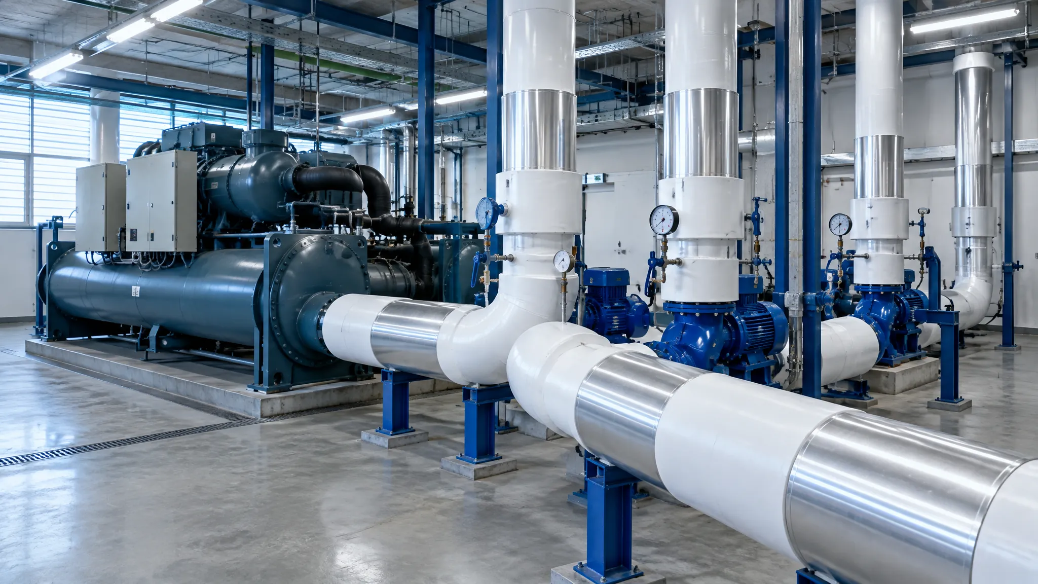
A chilled water system is a closed hydronic loop that carries heat out of a building in water. A chiller, or a heat exchanger in an energy transfer station where district cooling is used, cools water to 6–7 °C. Pumps push it through pipe to the coils in air-handling and fan-coil units. The coils warm it to 11–16 °C, and it returns to be cooled again (UFC 3-430-09, Table 2-1). For a piping buyer the useful form of that definition is four segments: plant piping, mains and risers, floor branches with terminal tails, and the condenser or district side. Each segment carries different water, holds a different pressure and falls in a different size band.
Key Takeaways
The Engineering Mindset’s animation below walks the same loop in motion: chiller evaporator to cooling coils and back, with the condenser water loop rejecting heat at the tower. Watch it before the segment-by-segment reading that follows.
The chiller’s refrigeration cycle pulls heat out of the water passing through its evaporator, and that water leaves as chilled water supply. UFC 3-430-09 Table 2-1 sets the design supply at 42–45 °F (6–7 °C) and the return at 52–60 °F (11–16 °C). Pumps move the supply through the distribution pipe to cooling coils in air-handling units (AHU) and fan-coil units (FCU). Room air crosses the coil and the warmer return travels back to the evaporator. The condenser side rejects that heat outdoors, to air or through a separate condenser-water loop at 29 °C supply and 41 °C return on the same UFC table.
Flow is not a free variable. The UFC table states the formula: gpm = 12,000 Btu/ton × tons ÷ (500 × (return − supply)). Reduced, that is 24 ÷ ΔT gallons per minute per ton: 2.4 gpm/ton at a 10 °F ΔT, the ARI 550/590 rating basis at 44 °F leaving water (CoolTools Chilled Water Plant Design Guide, Table 3-3), and 1.6 gpm/ton at 15 °F. Both figures are derived, not quoted.
The second one matters: ASHRAE 90.1 §6.5.4.7 requires coils selected for a 15 °F or higher water-side difference with leaving water no colder than 57 °F at design, exceptions aside (quoted in Trane Engineers Newsletter 48-2). Every pipe downstream of a 15 °F coil carries one third less water than at 10 °F.
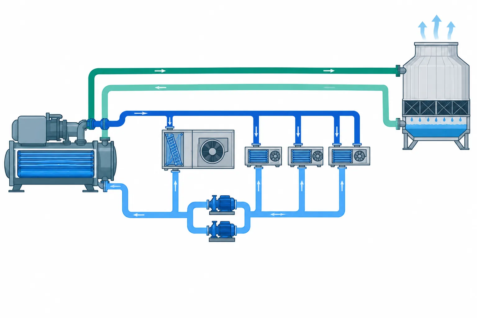
Plants with more than one chiller have traditionally split the loop in two. The primary loop serves the chillers with constant-volume pumps. The secondary loop serves the building with variable-speed pumps. A short length of common pipe joins them so each loop can run at its own flow (CoolTools guide, hydronic distribution). When secondary flow exceeds primary, return water crosses the common pipe and warms the supply. When return water comes back colder than design, the chillers cannot load fully; the guide calls this low delta-T syndrome and traces most of it to coil control valves.
The two loops also run at different temperatures: BSRIA BG 30/2007 Sheet W1 gives primary circuits 6–12 °C and secondary circuits 10–15 °C, so a secondary-side branch rarely sees the coldest water in the plant. Decoupler dimensions, variable primary flow and the bypass rules are on the primary versus secondary loops guide; this page stops at the boundary.
Chiller vendors describe this system from the chiller outward. A pipe supplier reads it the other way: which segment is being bought, what water it carries, what pressure it holds, and whether Φ20–Φ110 covers it. Size frames below use ASHRAE 90.1 Table 6-8, which caps design flow per pipe size from 2½ in upward by annual operating hours. The CoolTools guide that produced that table states it was developed on steel and copper pipe and that plastic pipe friction will differ (CoolTools guide, §6). The bands frame the segment; they do not size a plastic branch.
| Segment | Design water temperature (°C) | Pressure regime | Size frame (ASHRAE 90.1 Table 6-8) | Material family and IFANnova scope |
|---|---|---|---|---|
| Plant and primary loop (evaporator piping) | 6–7 supply, 11–16 return (UFC); primary 6–12 (BSRIA) | Plant pumps plus building static head (UFC: friction and static heads) | Table 6-8 flow caps 2½–12 in; velocity caps only over 12 in | Steel and copper basis; outside IFANnova range |
| Secondary mains and risers | 10–15 secondary circuits (BSRIA) | Static head of every served floor; high-rise may exceed 2000 kPa (IEA) | Table 6-8 flow caps 2½–12 in | Above Φ110; not made by IFANnova |
| Floor branches and FCU/AHU tails | 10–15 secondary circuits (BSRIA) | Floor static head plus coil pressure drop; PN class checked against it | No Table 6-8 cap below 2½ in; BSRIA steel ≤50 mm 0.75–1.5 m/s | UPVC 806 PN16 and HDPE Φ20–110; PPR PN20 20–32 mm: IFANnova |
| Condenser water (water-cooled plants) | 29 supply, 41 return at 3 gpm per ton (UFC) | Tower circuit; friction and static heads (UFC) | Table 6-8 applies to condenser water too | Outside this guide’s scope |
| District cooling ETS interface | Fixed by the provider’s connection terms, not a handbook | District side about 1000 kPa; building side may exceed 2000 kPa (IEA) | Heat exchanger and meter; direct or indirect connection | Network side utility-owned (Conditions of Service, as published) |
Source: UFC 3-430-09 (28 July 2025) Table 2-1; BSRIA BG 30/2007 Sheet W1; CoolTools Chilled Water Plant Design Guide (December 2009) Table 6-8; IEA DHC Connection Handbook (Annex VI); Dubai district cooling utility Conditions of Service, DCS Rev 04 (2009); IFANnova catalogue data. Compiled 12 September 2026.
Our own line sits in the third row and nowhere else. UPVC 806 PN16 runs from 20×2.0 to 110×7.2 mm and HDPE from 20×2.3 to 110×10.0 mm, both in 4 m lengths with fittings across Φ20–Φ110. PPR PN20 stops at 32 mm. We neither make nor subcontract mains above Φ110. Material selection, sizing method and insulation for the branch segment are covered on the chilled water pipe materials, sizing and insulation page.
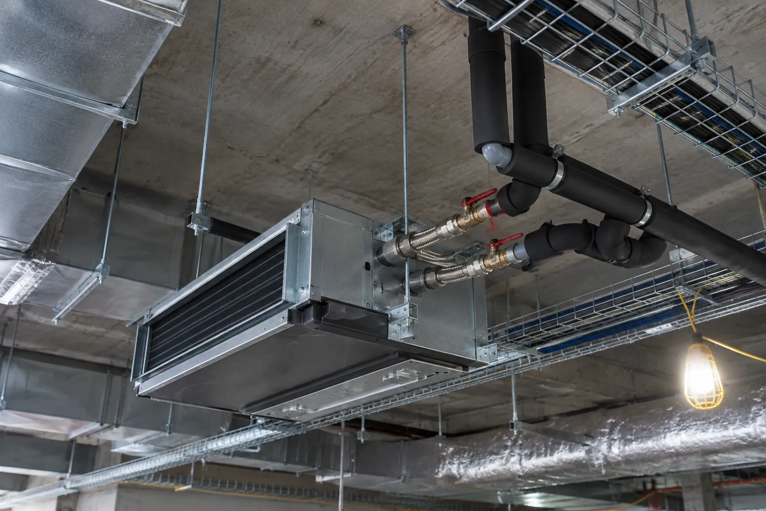
UFC 3-430-09 Table 2-1 states the chilled water pressure in one line: it depends on friction and static heads. The chiller sets the temperature; building height sets the pressure at the bottom of the riser. The IEA District Heating and Cooling Connection Handbook gives the scale. Plate heat exchangers on the district side are typically designed for 1000 kPa (150 psig). The building side of a high-rise may have design pressures exceeding 2000 kPa (300 psig). A PN16 branch pipe carries a nominal 16 bar (1600 kPa), so which floors it can serve is a static-head question, answered before the material question.
ISO 1452-2:2009 selects the PN class of PVC-U pressure pipe for water up to and including 25 °C (clause 7.2), so a 6–16 °C loop sits inside the window the class already assumes. The Georg Fischer PVC-U system specification gives 0–60 °C as the service range. On our own range: UPVC 806 is catalogued PN16; the HDPE pipe body is marked GERMANY STANDARD DIN8077/8078 and its pressure class is awaiting internal confirmation, so ask for the test certificate rather than reading the marking as a rating. How a PN class is proven on site is on the pressure testing plastic pipe page.
A pipe carrying 7 °C water through a ceiling void is colder than the dew point of the surrounding air in a humid climate, so water condenses on its surface. The National Insulation Association states the design goal in one line: keep the surface temperature above the dew-point temperature of the surrounding air. That applies to plastic as much as to steel. A low-conductivity wall slows heat gain; it does not lift the surface above dew point.
The code floor is thinner than the condensation requirement. ASHRAE 90.1-2019 Addendum aq, Table 6.8.3-2 asks 13 mm of insulation on pipe under 40 mm and 25 mm from 40 mm up, for 4–16 °C fluid at a 0.030–0.039 W/m·K conductivity basis. Footnote b states those thicknesses are based on energy efficiency considerations only, with vapor retarders or additional insulation sometimes required for surface condensation. What fails first in practice is the barrier, not the thickness; the vapour barrier failures guide covers the failure modes.
Footnote c of the same table waives insulation for direct-buried cooling system piping, which is the case that applies to buried chilled water lines in HDPE. No authority we could open publishes a Gulf dew point or thickness table, so this page gives the criterion and the code floor only.
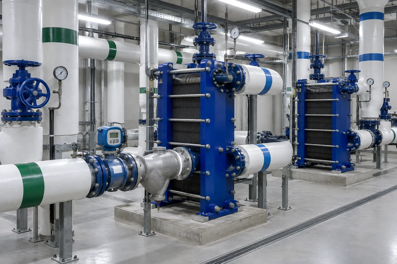
In Dubai the chiller is often not in the building. District cooling is one of the nine programmes of the Demand Side Management Strategy the Dubai Supreme Council of Energy launched in June 2013. Its target is a 30% cut in energy and water demand by 2030. In a district-cooled building the system boundary moves to the energy transfer station (ETS), where the provider’s network delivers chilled water and takes the return; the building-side loop starts there.
The published Conditions of Service of Dubai’s district cooling utility (DCS Rev 04, 2009, which the utility states it may revise) put the division in contract terms. The building owner provides a secure ETS room; the utility supplies chilled water to the ETS and returns it from there; only an authorised utility representative may tap or operate valves on a chilled water main.
On the connection itself, the IEA handbook describes indirect connection through plate heat exchangers and direct connection through a decoupler to the coils, with heat-exchanger duty set by the temperature and pressure differentials the specific district system dictates. For the branch segment, supply temperature, ΔT and available pressure are therefore contract values from the provider, and the piping RFQ should quote them from the connection agreement.
A quotation for floor branches and terminal tails is only as good as the five facts sent with it. UFC 3-430-09 clause 4-2.1.5 requires chilled water sizing not to exceed the ASHRAE 90.1 maximum flow, which Table 6-8 bands by annual operating hours.
What IFANnova can state first-party today is item one’s spec range (UPVC 806 PN16 and HDPE, Φ20–Φ110; PPR PN20 at 20, 25 and 32 mm) and item five’s markings. MOQ, price basis, production and sea lead time, sampling terms and certificate numbers are advised per project, because they depend on size mix, container plan and destination port. Send the five facts above and the quotation comes back against them. A worked sizing example shows how branch diameters fall out of the coil load.
Treat a chilled water system as four piping segments, not one product: plant, mains and risers, floor branches with terminal tails, and the condenser or district side. Buy the branch segment on static head and design ΔT first, insulation and vapour barrier second, and material third; the order changes only when a district provider’s connection agreement, not a handbook, fixes the temperatures.
If your segment is Φ20–Φ110, the spec range and markings above are the start of a quotation. If it is a main above Φ110, it is not a pipe we make.
Chilled water circulates inside the building at 6–7 °C supply and 11–16 °C return; condenser water rejects the chiller’s heat to a cooling tower at 29 °C supply and 41 °C return, 3 gpm per ton (UFC 3-430-09 Table 2-1). They are separate loops and never mix.
UFC 3-430-09 Table 2-1 gives 42–45 °F (6–7 °C) supply and 52–60 °F (11–16 °C) return; BSRIA BG 30 Sheet W1 gives 6–12 °C primary and 10–15 °C secondary circuits. District-cooled buildings take the provider’s contract values instead.
The system boundary moves to the energy transfer station: the provider owns the network side and fixes the temperature and pressure differentials, and the building-side piping starts at the heat exchanger or decoupler (IEA DHC Connection Handbook; the utility’s Conditions of Service as published).
In the branch segment, within its class: ISO 1452-2 selects the PN class of PVC-U for water up to 25 °C and Georg Fischer rates PVC-U for 0–60 °C service. ASHRAE 90.1 Table 6-8 flow caps were built on steel and copper, so plastic friction is checked separately.
Yes. ASHRAE 90.1 Table 6.8.3-2 asks 13 mm below 40 mm pipe and 25 mm from 40 mm up for 4–16 °C fluid on energy grounds alone, and condensation control needs the surface above dew point (NIA); a low-conductivity wall does not achieve that by itself.

